The subject this time is the Z-80 Block instructions. There are block instructions for I/O, search (compare), and transfer (assignment). We listed the block I/O instructions last lesson but they are detailed again in chart 1.
Before we look at the instructions, we need to review one of the Z-80’s flags. It is the parity/overflow (P/V) flag and is an overworked little devil, as it keeps track of two conditions, depending upon the instruction being executed. I gave you a chart of affected flags, by instruction, in lesson 5 (if you need lesson 5, contact TDM for a back issue!)
Overflow is similiar to carry except that it occurs only when there is a carry from bit 6 to bit 7, of the accumulator, in signed arithmetic. The effect of an overflow is to change the sign bit of the accumulator. Overflow can be detected by use of the carry flag, but it is more difficult.
The use of the P/V flag we are interested in is Parity. Parity is either even or odd and is simply a count of the set bits in a byte or register. An even number of set bits results in even parity and a set parity flag. Parity is indicated with the logical, rotate, I/O and all block instructions.
The actual use of the parity flag in the block instructions is to indicate when the BC register pair has been decremented to 0 (see below). You will recall that 16 bit decrements do not affect the zero flag. Since the Z-80 can indicate BC=0 in the P/V flag, it could have done the same in the zero flag, except that the zero flag already has a use in the block instructions (see below).
There is one last piece of information we need in order to use the block instructions; how and which registers do we need to set-up? All the register pairs are used as follows.
The BC pair is a 16 bit counter. The parity flag is set and the block instruction is terminated when BC=0. There is no 8 bit counter allowed, except for the I/O instructions, where B serves the purpose.
The DE pair is a DEstination pointer for block memory transfers.
The HL pair, as usual, is a memory pointer for all the block instructions.
All the block instructions decrement BC and either increment or decrement DE and HL, according to the type of instruction. The third letter of the mnemonic will be ‘i’ for and increment or ‘d’ for decrement.
If the fourth letter of the mnemonic is an ‘r’, then the instruction is functionally the same as the the 3 letter version, except that the instruction repeats until a counter has been decremented to 0.
Now for the instructions. I have listed the instruction (a few samples for each group) with its operation broken into ‘equivalent’ instructions, next to it. REMEMBER, the equivalent instructions are for clarification ONLY and are not executable!
The first set is the completion of our I/O instructions, from last lesson.
      Ini                        Indr
---------------            ---------------
 Ld (HL),(C)               Loop Ld (HL),(C)
 Inc HL                         Dec HL
 Dec B                          DJNZ Loop
Notice that the block instruction is the same as the In r,(C) instruction from last lesson. The difference is that r can only be (HL) and the B register is a counter, hence the above ‘equivalent’ instructions.
Note also, how the auto repeat works. Since the repeat is part of the instruction, no other operation can occur in the loop (except, of course, interrupts–but that’s next lesson). The loop is not exited until B=0.
The block Out instructions are the same except that the byte pointed to by HL is moved Out port (C).
The block search instructions are a variation of our old friend Cp (compare), as follows:
      Cpd                        Cpir
---------------            ---------------
 Cp (HL)                   Loop Cp (HL)
 Ret Z                          Ret Z
 Dec HL                         Inc HL
 Dec BC                         Dec BC
                                Jr NZ,Loop
Note the additional exit point (Ret Z). These are called the block search instructions, as they will look at each byte and set one of two flags. The zero flag is set if A=(HL), (there is no Ret to anything) or the parity flag is set if BC=0. Since the Ret Z is for demonstration only, it is important to know that the operations on BC and HL will occur, even if a match has occurred. Therefore, you may need to adjust a pointer, after a match.
For example, assume the accumulator contains FFh, HL contains 4000h and BC=06h. This is the section of memory to search:
Address  Contents
 4000h     00h
 4001h     09h
 4002h     F9h
 4003h     FFh
 4004h     C9h
 4005h     E1h
The search will end with the match at address 4003h and the registers will contain:
A  = FFh
HL = 4004h
BC = 01h
The zero flag will be set, to indicate a match, and the parity flag will not be set, as we did not reach zero in BC.
The last group of block instructions are for memory transfers (move one block of memory from here to there). They are essentially a variation on the assignment instructions (Ld) except that they work on two memory locations, instead of a register and a memory location.
The registers must be set-up in advance for these instructions to work properly, as follows:
BC = size of block to transfer
HL = first byte address of block to transfer
DE = first byte address of new location of
     block, after transfer (DEstination)
Once the registers are set-up, the instructions work like this:
      Ldd                        Ldir
---------------            ---------------
 Ld (DE),(HL)              Loop Ld (DE),(HL)
 Dec DE                         Inc DE
 Dec HL                         Inc HL
 Dec BC                         Dec BC
                                Jr NZ,Loop
Note that we have only one exit to the loop, the case where BC=0.
The following routine should be placed in your 0 REM statement, to move your MC above Ramtop:
“` Move Ld HL,Base ;start address of your MC Ld DE,Ramtop+1 ;destination address above ;Ramtop, where your MC will run Ld BC,Length ;length of your MC routine Ldir ;move your MC above Ramtop Ret ;back to Basic “`
One important point, any absolute addresses (Call nnnn, Jp nnnn, etc.) must be adjusted to indicate locations within the new block. The usual method is to assemble your MC to run at its correct location, then place it in the Rem statement for storage and SAVEing. This is the better method of saving and running MC from high memory on the TS1000, than the method I gave last lesson. See if you can make a small change in the above routine to move your MC from high memory to your 0 REM statement, using the Lddr instruction.
The last caveat to watch for with transfers is overwriting a portion of your MC, if the blocks overlap. When there is an overlap of blocks, the bytes can often only be moved in one direction or from one end of a block. For example, the routine above moves a block from start to end. It could just as easily been moved from end to start, using the Lddr instruction, if the pointers indicated the end of each block.
The astute reader will begin to see some possibilities in these instructions, as they are fast and very powerful. You could, for instance, write your own ‘find and replace’ routines, create ‘instant’ screen swaps or even animate a small section of the display (sprites). I’ll leave you with your imagination and the following routine.
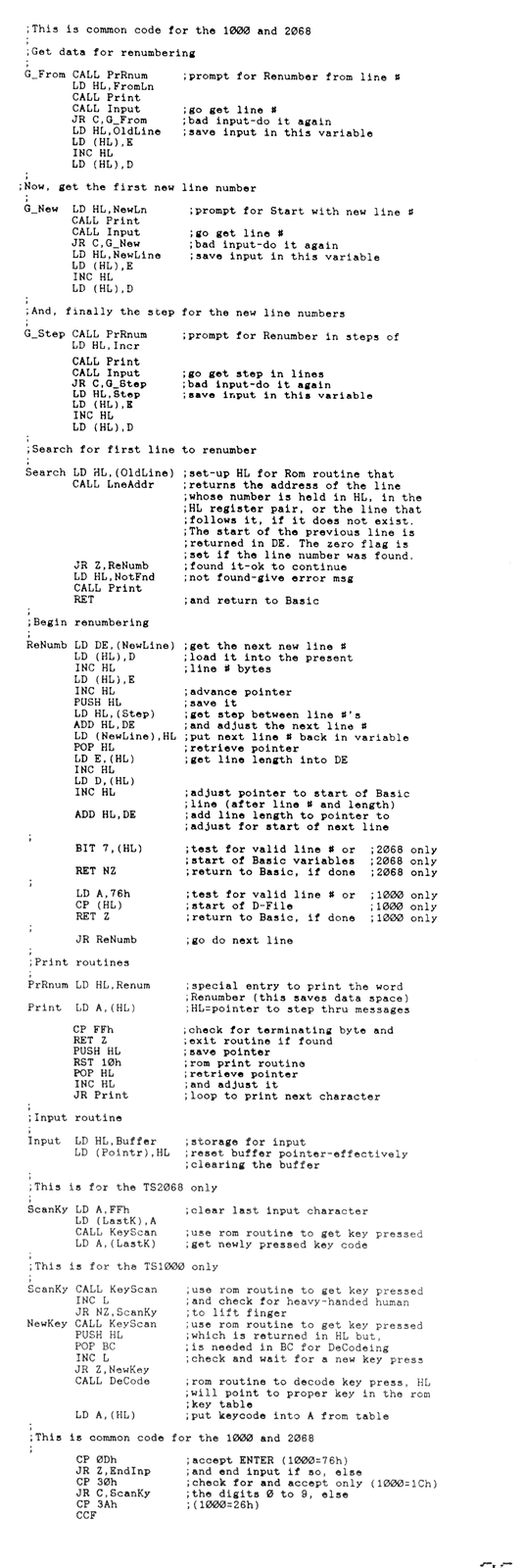
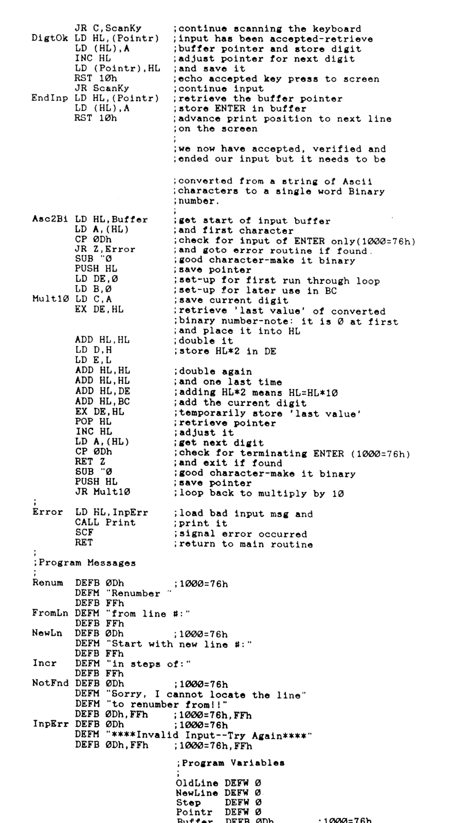
Our routine deviates from the instructions of this lesson. It is a renumbering routine for Basic programs and is given as a demonstration of what is possible and give you some more technique. It will renumber any Basic program from a stated line (which must exist) to the program end.
Many of the routines can be used in other programs, such as the input routine. It uses some error checking in order to avoid any non-numeric input. It also gives the method of converting an Ascii string of digits to a binary number for use in calculations. It does however lack a backspace or delete. Can you see how to add it by reading one additional key press and adjusting the buffer pointer? Notice how the carry flag is used to indicate an error. Also, note that space must be left at the end of the routine for the input buffer. Do you want prompts anywhere on the screen? Run the Input routine with a PRINT USR address!
Note that this program is written in rather large modules, that fall through to the next one. It is extremely hard to debug a program written in this fashion, unless you are using routines that are known to be bug-free. Can you see the obvious places for break-points, in order to test for debug purposes?
Note how we reuse the string data for the Renumber prompt. But, enough of this. Here’s the routine:
RENUMBER BASIC PROGRAM
“` ;Basic system variables: Prog Equ 5C53h LastK Equ 5C08h ; ;ROM calls: KeyScan Equ 02E1h ;TS1000 = 02BBh LneAddr Equ 16D6h ;TS1000 = 09D8h DeCode Equ 07BDh ;TS1000 only ; Org FC00h ;TS1000 = 7C00h ; ;Test for a Basic Program to renumber for the TS2068 ; Start LD HL,(Prog) ;no program line number has the BIT 7,(HL) ;7th bit set in high byte of line ;number, but start of VARS does RET NZ ;no program-return to Basic ; ;Test for a Basic Program to renumber for the TS1000 ; Start LD HL,407Dh ;start of Basic program area will LD A,76h ;contain an ENTER (chr$ 118) if no CP (HL) ;program as will be first character RET Z ;of the display file “`