
THE SPECTRUM EXPANSION CONNECTOR
One of the first questions asked after the ROM conversion is made on the 2068 is “can I run peripherals designed for the Spectrum?” . . .the answer is maybe yes, maybe no. The first thing we must look at is just how the Spectrum makes its connection. The following is the expansion connector from the viewpoint of the 2068 with its parallel point on the Spectrum: (aligned on the slot)
NON-COMPONENT SIDE                    COMPONENT SIDE
2068 EDGE CONNECTOR #                 2068 EDGE CONNECTOR #

2068              SPECTRUM            2068          SPECTRUM

GND                1 --               GND            1 --
SPK/TAPE OUT       2 A14              EAR            2 A15
+15V               3 A12              A7RB           3 A13
+5V                4 +5V              D7             4 D7
NC                 5 +9V              DZ IN (NC)     5 NC
SLOT               6 SLOT             SLOT           6 SLOT
PWR GND            7 0V               D0             7 D0
PWR GND            8 0V               D1             8 D1
CLK                9 CLK              D2             9 D2
A0                10 A0               D6            10 D6
A1                11 A1               D5            11 D5
A2                12 A2               D3            12 D3
A3                13 A3               D4            13 D4
A15B              14 IORQGE           INT           14 INT
A14B              15 0V               NMI           15 NMI
A13B              16 VIDEO            HALT          16 HALT
A12               17 Y                MREQB         17 MREQ
A11               18 V                IORQB         18 IORQ
A10               19 U                RDB           19 RD
A9                20 BUSRQ            WRB           20 WR
A8                21 RESET            BUSACK        21 -5V
A7                22 A7               WAIT          22 WAIT
A6                23 A6               BUSRQ         23 +12V
A5                24 A5               RESET         24 12Vunsmooth
A4                25 A4               MI            25 MI
DZ OUT(NC)        26 ROMCS            RFSHB         26 RFSH
R                 27 BUSACK           EXROM         27 A8
G                 28 A9               ROSCOS        28 A10
B                 29 A11              BE            29 NC
BUS ISO(NC)       30 --               IOA5          30 --
VIDEO             31 --               SOUND         31 --
GND               32 --               GND           32 --
As you can see the things that do match are D0-D7, A0-A7, +5v, and most of the Z80 control line. There are a few of the lines that are buffered on the 2068 (indicated by a B at the end of the label) but not on the Spectrum. In most cases this buffering makes no major difference. A second look reveals that the 2068 makes a nearly complete match with the ZX81family with the exception of the +9v line. However, the Spectrum did not follow this convention as a number of address lines are moved around plus added voltages make a significant difference.
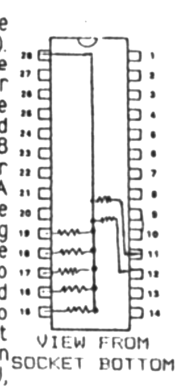
There is one hidden but major difference in the data lines that is also significant. In voth the Spectrum and ZX81 each data line has a 10kohm pullup resistor to the +5v supply. What this means is that in some software that uses interrupts that the data lines will not be properly configured. This is a limited amount of software and generally will not be of any major importance. It may effect some hardware operation. The fix is simple enough. In the 2068 the easiest place to add the pullup resistors is the EXROM socket (that is the other socketed chip located above the cartridge connector toward the rear of the computer). This can be accomplished by taking the EXROM from its socket and adding another socket (I would recommend a low profile machine pin type) which has been modified by adding either individual resistors (1/8 watt only will fit) or a SIP resistor network to the underside as illustrated. A pullup resistor is not added to D2 as there is already one in the 2068. After making the mod to the socket (take care to keep the resistors close to the socket) plug it into the EXROM socket in proper orientation and reinset the EXROM. This should have no effect on 2068 or Spectrum operation. At this point this data line mod is not known to be incorporated on the Romswitch, EMU, or SWITCHBOARD. Check your unit to verify. You may find it simpler to add a SIP resistor network directly to the data lines of one of those conversion units. This is the fix that is necessary to let at least one pice of software run (Checquered Flag from Psion) and may fix others. I reiterate that this only impacts a limited amount of software.
This article is intended only to provide an overview of the Spectrum bus and as a starting point for your own consideration of peripherals that you are considering purchasing from England. It would appear possible with a little work to make an adapter to get things in order as most voltages could be derived from the +15 volt supply. Y, V, U signals are video signals…luminance/sync, red-yellow, and blue-yellow respectively. IORQGE is a variant of IORQ. With A0-A7 in line and D0-D7 squared away most devices at ports up to 255 should work providing that the power is derived from the +5v line. It is best to proceed with caution and I would appreciate any input that you might add to these notes.
And now for a few notes on recommended reading for those that might be interest in hardware (either build your own or purchased).
SPECTRUM HARDWARE MANUAL by Adrian Dickens, Published by Melbourne House. This book packs into 124 pages just about all you could want to know about the Spectrum machine up through Issue 3. Includes schematics and parts list with a good explanation of the inner workings of the machine. Plans are included for Centronics interface, joystick, and A/D converter. I would even recommend it to those without Spectrum conversion as the technical similarity to the 2068 machine is sufficient to be helpful. A MUST BOOK for your library if hardware is your thing. Available from Zebra Systems, 78-06 Jamaica Avenue, Woodhave, New York 11421 for $14.95 plus $3.00 P&H.
EASY ADD ON PROJECTS FOR YOUR SPECTRUM, ZX81 & ACE by Owen Bishop, Published by Bernard Babani. This little book is well worth the $6.50 plus $.75 P&H as a starting point for a number of hardware projects for the ZX variant machines. As the projects are described in thorough detail with clear illustrations. Some of the projects detailed are a picture digitizer, light pen, a weather station and more. Most of the components listed are available here or at least their equivalents. Available from Electronic Technology Today, Inc., P. O. Box 240, Massapequa Park, NY 11762-0240.
That’s all for this time. If you have any comments or additions, I’m always glad to hear them.
Jack Keene
[address omitted]