
A Follow-up
As can be expected with any major hardware upgrade, there are a few conflicts when the Oliger video system (see SWN #2:1 and 2:2) is used in conjunction with other equipment. Sadly, some manufacturers shed little light on what has to be done to make their add-ons compatible with other peripherals. This is not the case with the John Oliger Company. In the process of building up my Super-ZX, I found its illustrious proprietor most helpful in getting my system working harmoniously. Most of the information in this article was supplied by John in response to my many letters and phone calls, and since his schedule is already very busy I (Fred N.) agreed to “ghost-write” this article to summarize the fixes we and others have come up with to date.
ROM Chip Select
The most common conflict involves devices that use the ROMCS NOT line to disable the ROM. There are two reasons that a device would want to do this. The first is that the ZX/TS doesn’t fully decode the ROM address space, with the result that the ROM “echoes” in the 8-16K range. Any memory addition (64K packs, Hunter board) that employs this region of memory must force ROMCS NOT low when A14, A15 and MREQ NOT are low, and A13 is high (8-16K is being addressed). This usage of ROMCS NOT DOESN’T affect operation with the video upgrade, since its purpose is only to supply decoding absent in the Sinclair logic chip. This decoding is duplicated on video board “B” for EPROM “a” using gates in U1 and U2.
The other reason for using ROMCS NOT is to actually OVERLAY or MASK the ROM when certain addresses are paged. Any device that contains its own code to replace part of the ROM code has to turn off the ROM under these conditions. Devices that do this include the Memotech Centronics interface and the Compusa disk drive, quite probably several others. A problem arises with the video upgrade, because during normal operation you’re not even using the resident ROM; the modified ROM code in EPROM “a” is used instead. Therefore, the ROMCS NOT line from your outside device has to be patched in so that it controls the chip select on EPROM “a” instead of the original ROM.
Figure 1 shows how to accomplish this. As you can see, the solution is very easy, and involves only video board “B”:
1: Cut the line from the junction of U3 pin 9,10 and 11 to ROMCS NOT. Bridge the gap with a 1N4148 diode, cathode (banded) end towards computer ROMCS NOT.
2: Cut the trace between U4 pin 8 and Ea pin 22. Bridge the gap with a 680 ohm resistor.
3: Disconnect your outside device’s (e.g. Memotech interface) ROMCS NOT line, and connect it to Ea pin 22 instead.
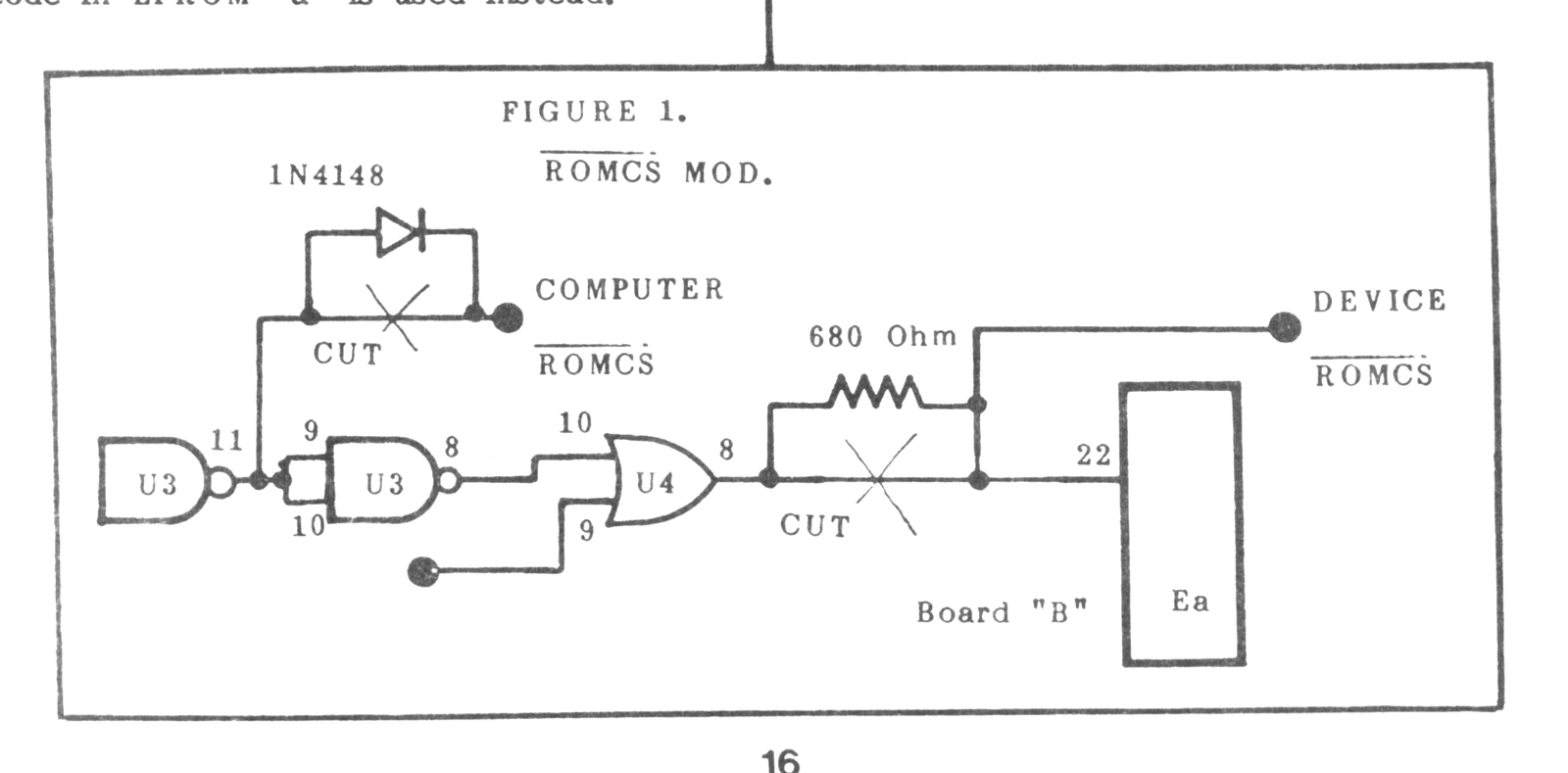
If you are using John’s expansion board, the required re-route of the interface’s ROMCS NOT line can be accomplished easily with a trace cut, and a jumper on board “B” to one of the unused pins on the expansion board (e.g. 24B), which we could call EaCS NOT. Note, however, that you cannot simply unplug the video boards to return to the normal Sinclair video system and still have your other peripherals work normally. The solution is to provide a switch to toggle between modes.
Switchable Video
Though the Oliger TI video system is vastly superior for most programs, there are some programs (especially machine-code games) that run far too fast to be usable. Or you might want to run Software Farm‘s “software-only hi-res” games or similar programs (which don’t work with Oliger video). For such software it would be convenient to have a single switch to toggle between normal Sinclair video and Oliger TI video. This is especially vital if you, like me, have built your system into a single enclosure, and cannot easily unplug the video boards.
John worked out a way to do this using a DPDT switch. If you also have to switch the out-going ROMCS NOT line as above, you’ll need a third pole. You could go one step further yet and add a fourth pole to switch the video output jack between the TMS9918A output and the normal ULA pin 16 output (or video driver, e.g. as detailed in SWN 1).
Since the mechanics of mounting the switch will vary according to your particular installation, I’ll leave the mounting details up to you. Try to mount the switch as close to the video boards as is practical. The electronics mods are quite simple, and are diagrammed in Figure 2. The changes are:
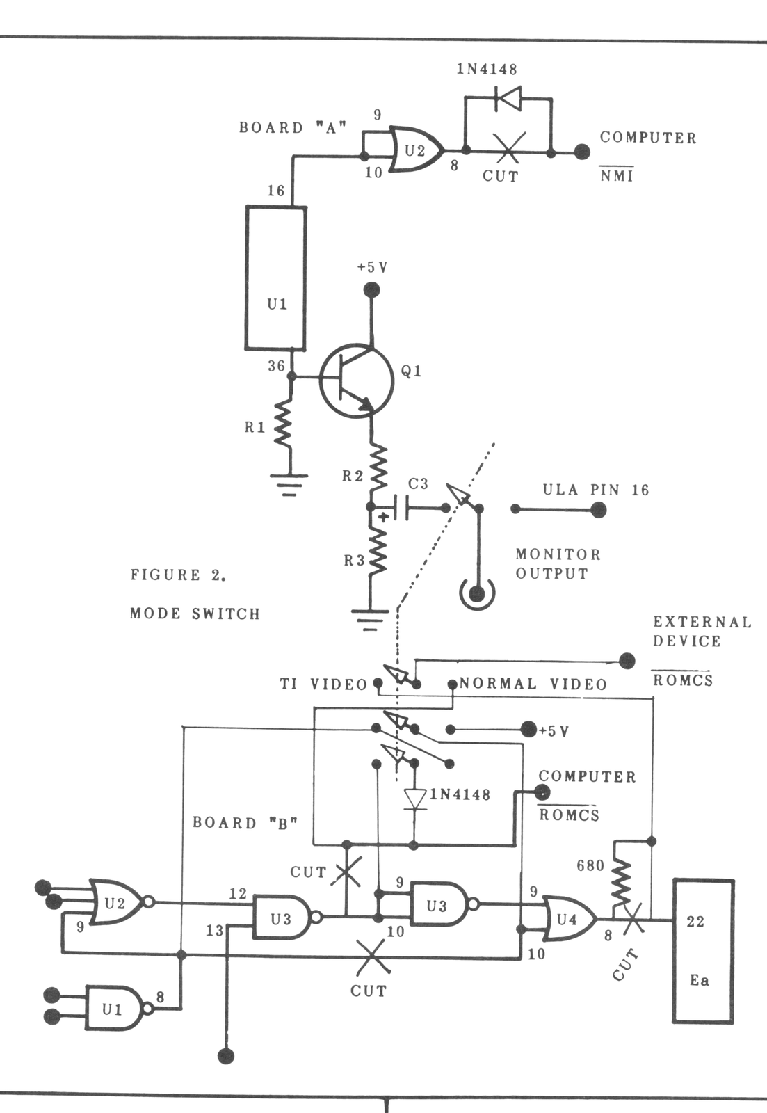
1: Cut the trace going to pin 8 of U2 on board “A”, and bridge the gap with a 1N4148 diode, cathode end towards U2 pin 8 (see Figure 3). This allows the normal video system to continue using the NMI NOT line when the TI video is disengaged. This is the only change required on board “A” unless you decided to also switch the video line.
2: On video board “B”, cut the ROMCS NOT line as described above. Don’t bridge the gap with the diode as before, instead run flying leads to each end of the cut and route them to the switch.
3: Cut the trace between the junction of U2 pin 9 and U1 pin 8, and U4 pin 9. Again run flying leads to both sides of the cut and route them to the switch.
4: If you’ll be using peripherals that control the ROMCS NOT line, install the 680 ohm resistor in line with U4 pin 8, and route the EaCS NOT line from Ea pin 22 to the switch.
5: Wire up the switch and the 1N4148 diode as shown in Figure 2. If you’re switching the video output jack, use the fourth pole of the switch for this purpose. Otherwise, you’ll have to supply two different output jacks for the two video modes.
Oliger Video Decoding
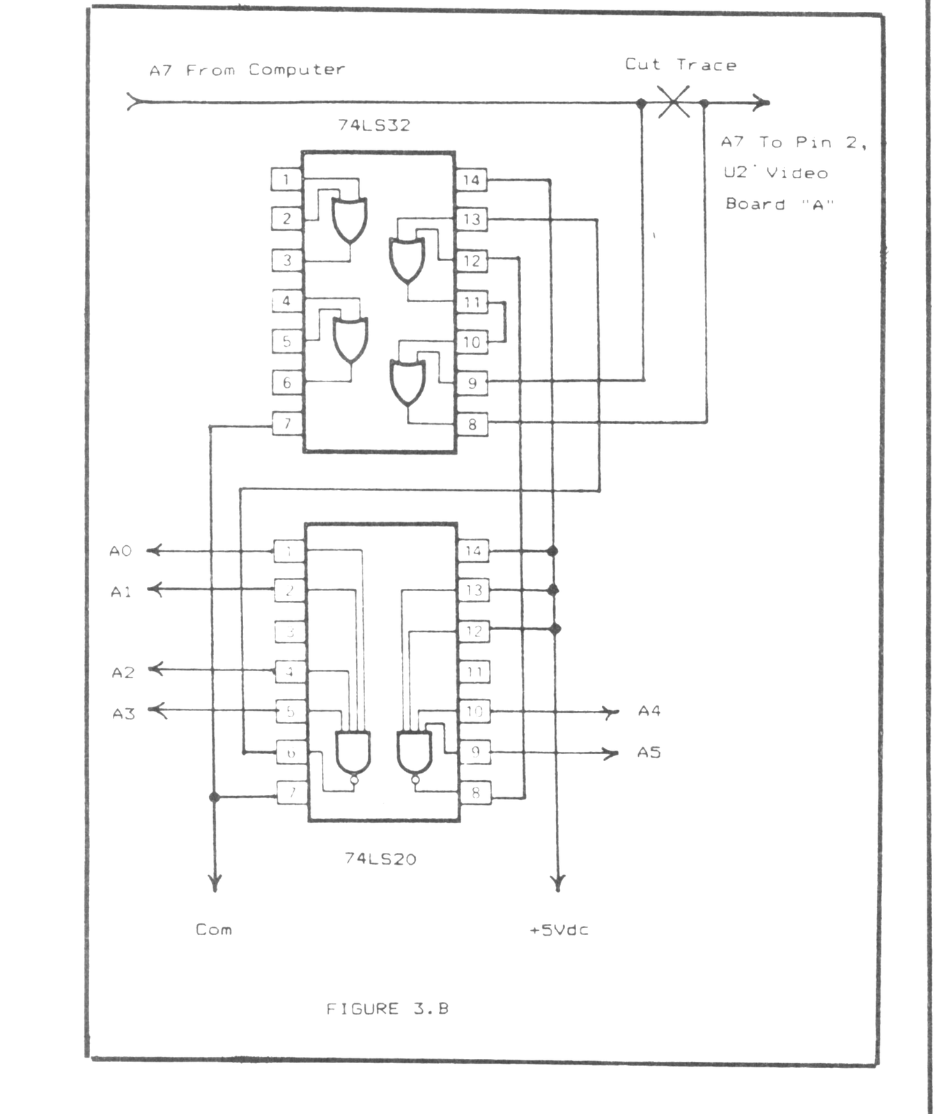
If you have the Compusa or Larken disk drive controller, the Westridge modem, possibly other I/O-mapped peripherals, you will have to make a minor decoding addition to your video board “A” so that the controller works properly in TI mode. This is because the I/O ports are not absolutely decoded. Peter McMullin supplies the two-chip mod detailed in Figure 3.B. Cut the trace to address line A7 (goes to U2 pin 7). Bridge the gap with Peter’s circuit. Peter writes, “I just piggy-backed both chips on top of U2 on board “A,” bending all but pins 7 and 14 straight out, then soldered wire-wrap jumpers as necessary. Works like a charm, with †Garden Variety LS’ [or HCT – fn] from your junkbox. (Who DOESN’T have some ’20s and ’32s kicking around, eh?) Note that two gates in the LS32 are left over, for other hacking purposes.”
For any device that uses the NMI NOT line (as Compusa), you will also have to diode OR the NMI NOT line if you haven’t already done so (see step 1 in the previous section).
Oliger Video & Memotech…
Many of you have the popular Memotech Centronics interface, and recent reports indicate that these units are again available. There are a few things you should be aware of when using this I/F with the Oliger video system.
If you want to use this interface with programs that use the BASIC printer commands (LLIST, COPY, LPRINT), you will have to re-route its ROMCS NOT line to EaCS NOT as described above. If your program pages the interface from directly from machine-code (as Memotext), this is technically un-necessary. It IS needed for Memocalc, since this program uses the BASIC commands and therefore needs the ROM overlay.
That takes care of the hardware aspect. Now let’s take a look at some software considerations. First the bad news: this interface uses the IN command at port 3F to send a character. This same port is used by the video system to communicate with the VDP’s video RAM (VRAM). Now the good news: under normal circumstances, this does not cause problems, since IN A,(3F) READS from the VRAM. The worst that can happen is that the accumulator (A register) will contain garbage after the character has been shipped out to the printer. It is very rare that you would need to preserve the contents of the A register after it has been sent, but if you do need to preserve it you should PUSH it onto the stack before using IN A,(3F) and then POP it back afterwards.
However, if you get into experimenting with the VDP’s powerful Graphics II mode, you will probably have the need to read from the VRAM using IN A,(3F). In this case, your command to read the contents of a VRAM location will also read printer status, and result in corrupted data. Your only recourse is to disengage or remove the printer interface when running software that reads the VRAM (such as my WA-TOR/TI, JOBASIC or PIXL-ATR programs).
The only way I’ve found to deactivate this interface without removing it is to switch the +5V power rail. I’ve had this arrangement on my unit for the past two years, and haven’t had any trouble. However, I should hasten to add that this is NOT John Oliger‘s idea, in fact I’ll be the first to admit that this is not “standard practice.” No one I’ve consulted about this felt there is any likelihood of damage, especially if you turn the interface on/off with system power disconnected. Still, if you’d rather not risk it, you’d be better off to physically remove the interface when its presence causes software conflicts.
…and Aerco
Similarly, the Aerco printer interface uses port 7F, which is also used by the video system to communicate with the VDP. This is the only known “irreconcilable difference” at this time. If you’re ambitious, you might consider re-mapping one or the other device. Alternately, consider a different interface for use with Oliger video.
Reports from the field indicate that no changes are required to make the Oliger video system work properly with the Aerco disk drive controller.
Speed it Up
With the Oliger video system, you eliminate dependence on the ULA logic chip as far as video generation is concerned. As a result, you can install a faster crystal and get your machine running even faster. At this writing, Tom Bent has successfully run his system using an 8.00 mHz. crystal, for a 23% overall speed increase. Though the tape routines are speeded up by the same amount, tapes saved on a standard machine still load using the faster crystal. (I wouldn’t try to go much faster, as the tape routines allow only about a 30% increase without changing the ROM routines.) Amazingly, it even works with the Compusa system! (Single density recommended; double density could be iffy.) In principle at least, the Z80A should work with an 8 mHz. crystal (4 mHz. clock), but a Z80B is recommended, if for nothing else than its improved load handling ability and lower overall capacitance.
Get in Sync
If you are losing horizontal sync (tearing) under certain conditions, or if your contrast is inadequate, remove transistor Q1, R2, and R3, and connect C1+ to VDP pin 36. (Technically, C1 could be omitted also, and may in fact be necessary with some monitors. However, its presence helps reduce the possibility that a monitor malfunction will blow the VDP). According to the TI manual, this “emitter follower” is not really needed. It actually reduces the video signal by some 30%, giving trouble with some monitors. Alternately, replace R2 with a short circuit, which will accomplish much the same effect as the direct connection.
The Soft Side
The TMS9918A video processor is an extremely flexible chip, allowing four different modes of operation. One of these, Graphics mode II, actually outperforms the TS2068’s video capabilities in some ways (e.g. eight times the vertical colour resolution, and a much more stable picture). I’ve successfully used this mode for high-res PLOT and DRAW, 64-column text screens, and rather impressive colour displays. Though these techniques were developed for my commercial “Extended BASIC” package for this board, I would be happy to share some of the details if there is enough interest.
Even in Graphics mode I (the mode selected when you initialize the Oliger system), there are some interesting possibilities not previously reported. For instance, you can define up to 128 user-defined characters in addition to your standard character set, in up to 16 different ink/paper colour combinations, using the formerly “illegal” character codes. These can be POKEd (or LDed) into the display file directly, for spectacular “space invaders” and other such creatures.
A third mode allows individual colour control over low-res block graphics (comparable to standard PLOT/UNPLOT) might be useful in certain graphic applications.
The fourth mode (“Text”) allows 40 column screens but is actually of limited usefulness, since up to 64 columns can be implemented in Graphics mode II, with far superior colour capabilities. Still, there are applications where this mode can be used to advantage. Sean Wenzel is currently working on a modem terminal program using this mode because of its higher speed (as compared to Mode II 64-column) and because most BBS’s use a 40-column format.
Now for some practical software tips when using this device. First is the matter of timing; the TMS9918A can’t quite keep up with even a 3.25 mHz. Z80 under certain circumstances. In general, sending data TO the VRAM (using OUT 3F,A) is not troublesome, but READING (using IN A,3F) seems to be a little balky. I found that two no-ops (NOP) between setting the VDP address pointer (RST 38) and reading from VRAM (IN A,3F) gives enough settling time. If you speed up your machine to 4 mHz., you should probably use 3 NOPs or their equivalent (12 T states) between RST 38 and reading from VRAM, although present indications are that two are adequate.
The EPROM “a” code as published by John Oliger only updates the screen every fourth frame in SLOW mode. Although this is a big reason why the unit runs almost as fast in SLOW as in FAST, it also causes a certain jumpiness in fast graphics, screen fills, and so on. This can be improved considerably by updating the screen every other frame, without seriously compromising speed. You can do this by changing the commands at 006D and 1E76 to LD A,FE (instead of FC). You could go one step further and update at every frame by changing the argument to FF. The drawback is that SLOW mode will now be only (?!) about twice as fast as normal. Lastly, you could change your EPROM “A” code to allow a selectable update rate with a POKE to 65535. Contact me for the details. (If you’re in the US, don’t bother with a SASE; American stamps don’t work from here.)
It is not completely obvious from the listings in SWN 2:2 how to change the default border colour. This is determined by the low nybble (second digit) of the data byte at 1E07. (The high nybble is the ink colour in “text” mode only.) Unfortunately, provisions weren’t made to change this from BASIC. Ink and paper default are set by the command at 1E45, where the high nybble of the code loaded into A specifies paper, and the low nybble specifies ink colour. I chose to make this 1F instead of F1, so that software designed for the “normal” black-on-white screen would come up looking normal, without first having to change the colour with USR 7881. I changed the border colour to gray (1E07 holds FE) so that it’s immediately obvious when you’re in TI video mode. (Besides, it looks nice.) Also consider grey as a colour for your usual characters, reserving white for high-lighting.
Peter McM also pointed out that if you’re using the Bent ROM as a starting point for burning your EPROM “a”, and are using John’s tape, you will have to change the command at 0002 so that it again reads LD HL,8000 if you want the normal 16K memory initialization. This is because John’s tape POKEs a 7F to 0004, assuming the original ROM which loads HL with 7FFF and later increments it. Other than that, Tom’s improved ROM code works fine. I especially like the FAST mode initialization, since this keeps your LOAD or SAVE command on the screen while performing tape operations.
Some of John’s lower case characters could be improved, particularly “m”, “w” and braces . For “m”, try the sequence 00 00 68 54 54 54 44 00, and for “w” try 00 00 44 54 54 54 28 00. For the braces, try 00 04 08 08 10 08 08 04 and 00 20 10 10 08 10 10 20. I also modified the symbols to agree with Memotext convention (personal taste). For custom character sets, study John’s code at 1E16 (SNGN) to understand how to initialize the VDP’s pattern generator in Graphics mode 1. Peter McMullin has designed several custom character sets, let us know if you’d be interested in seeing these.
Compatibility problems with existing software presently seem limited to XFORTH (and also, of course, the TREE-FORTH EPROM), though there may be a very few others. All versions of Hot Z work great, except for a problem when using its built-in tape routines. This is because it jumps into the middle of John’s patch in the end-check routine. The fix is the same for all versions, and simply entails changing JP 0206 to JP 0201 (making this change doesn’t affect operation in normal video mode). The address of this command varies according to the version. In the standard Hot Z II, 16K and 64K versions, this is at 5B11. In Hot Z-E V1.72 this is at 328A. If you have a different version, write JP 0206 somewhere in memory and use the string-search command to locate this statement.
Lastly, a mention of some TMS9918A oddities I’ve discovered. Presumably these apply to other such boards also (e.g. Colorsin and Kolorworks). Colours (i.e. not white or grey) have a decidedly grainy appearance. If you plot a horizontal line (as with JOBASIC), you’ll find that there is a 3:2 pixel relationship. Every third pixel plotted does not actually produce a new pixel on the screen; instead, the last pixel plotted simply gets a little wider. Oddly enough, this is more pronounced on monochrome monitors.
Some systems have initialization trouble, and come up with a blank screen after reset. This appears to be a loading problem, as it goes away when you replace all possible LS chips with HCT types.
White and grey characters have a multi-color “rainbow” look on colour monitors. This is due to the TMS9918 chip itself; TI simply could not include the necessary “trap” (filter) that would be necessary to correct this. Peter McMullin is contemplating working up a “retrofit” board that employs an RGB version of this chip, plus the necessary trap and other circuitry to give composite video output. We’ll let you know if/when this materializes.
If you want more information on the software aspects of this amazing chip and truly unique add-on, LET US KNOW! We’d be happy to bring you the “gory details”, but only if YOU say you want them!