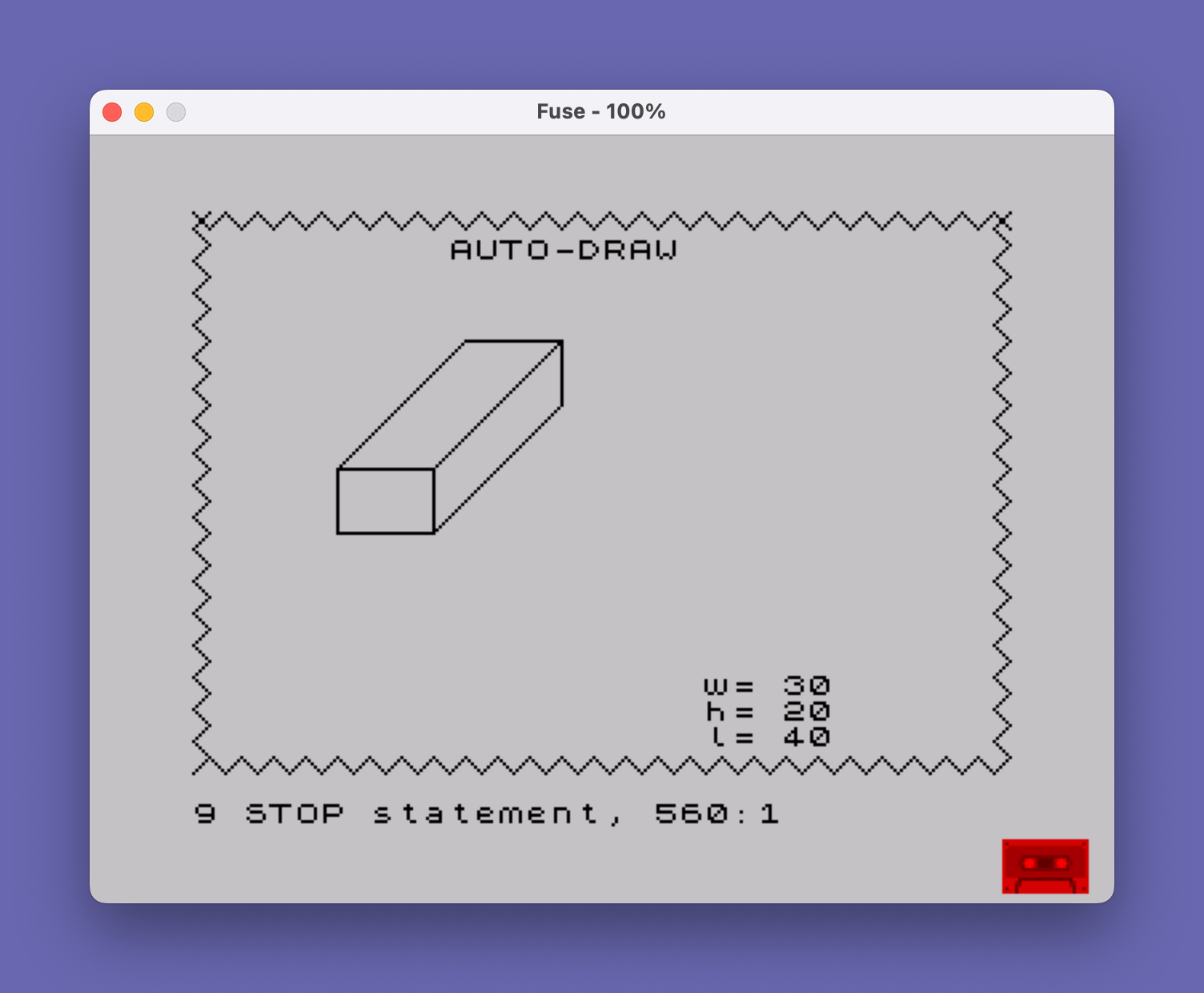
This program draws a three-dimensional box wireframe on screen using PLOT and DRAW commands, accepting user-supplied height, width, and length values. After rendering the box, it decorates the screen border with a repeating diagonal zigzag pattern drawn along all four edges using an ON ERR loop technique to detect when the drawing reaches the screen boundary. A separate, unreachable routine (lines 580–660) demonstrates an INK-colored horizontal fill pass through the interior of the box using POINT to locate a starting position.
Program Analysis
Program Structure
The program is organized into three distinct phases, with a fourth unreachable section appended as a work-in-progress:
- Box drawing (lines 300–360): Accepts three dimensions via
INPUTand renders a wireframe isometric box using a sequence ofPLOT/DRAWcommands, then prints dimension labels. - Border decoration (lines 370–550): Draws a repeating diagonal zigzag along each of the four screen edges, using
ON ERR GO TOto exit each edge’s loop when the drawing goes out of bounds. - Unreachable color fill (lines 570–660): A commented stub that would flood-fill the box interior with a colored horizontal stripe pattern; it is never reached because line 560
STOPs the program. - Save/Verify (line 9000): A standalone tape utility line not called from the main flow.
Box Drawing Technique
The isometric box is constructed from a fixed anchor point PLOT 75,95 using only relative DRAW commands. The front face is a rectangle drawn with vertical and horizontal segments, while depth lines are drawn diagonally using equal X and Y offsets (the l parameter), which gives an approximate 45-degree isometric projection. The back face and connecting edges are then completed to close the shape.
The dimension labels are printed at fixed screen positions (rows 18–20) using PRINT AT, which may overlap the border zigzag decoration drawn immediately afterward.
Error-Trapping Border Loop Idiom
Each of the four border zigzag sections uses the same pattern:
PLOTto a corner of the screen.- Two
DRAWcalls producing a V- or W-shaped zigzag step. ON ERR GO TOexit_line — sets an error handler to jump forward when the next draw goes out of bounds.- An unconditional
GO TOback to theDRAWpair, repeating indefinitely until the out-of-bounds error fires.
This is an elegant boundary-detection idiom: no coordinate arithmetic is needed to know when an edge is reached. The four corners used are (0,0), (0,175), (255,175), and (250,0), tracing bottom-left → top-left → top-right → bottom-right. The starting X for the bottom-right corner is 250 rather than 255, which may cause a slight gap at the final corner where the two bottom zigzags meet.
Unreachable Color Fill Routine
Lines 570–660 contain an unfinished fill routine that is dead code — line 560 halts execution before it can be reached. The routine attempts to find the left edge of the box’s top face using a POINT probe scan along row 100, then draws 48 horizontal lines with DRAW INK c;47,0 stepping upward. The color is set via LET c=4 (green in Spectrum/TS2068 color indexing). The loop variable n is reused across both FOR loops, with the second loop starting from the final value of n after the first loop exits — this is intentional, carrying the detected X position into the fill phase.
Notable Techniques and Anomalies
- ON ERR as a loop terminator: Using error trapping rather than bounds-checking arithmetic is a compact and effective TS2068 technique.
- ON ERR RESET at line 550: Clears the error handler before
STOP, which is good practice to avoid stale error handlers interfering with subsequent user interaction. - Dead code block (lines 570–660): The fill routine appears to be an experimental addition never integrated into the main flow. It could be activated by removing or commenting out line 560.
- Fixed anchor point: The box is always drawn anchored at
PLOT 75,95regardless of the entered dimensions, so very large values ofh,w, orlwill cause out-of-bounds errors during the box draw itself, before the border decoration phase. - Isometric approximation: Using equal X and Y for the depth parameter
lproduces 45-degree depth lines rather than true isometric (which would use a 2:1 ratio), giving a cabinet oblique projection appearance.
Variable Summary
| Variable | Purpose |
|---|---|
h | Height of the box (vertical extent) |
w | Width of the box (horizontal extent) |
l | Depth/length of the box (diagonal offset) |
c | INK color index for fill (set to 4, green) |
n | Loop counter; reused as edge-scan X position and fill row index |
Content
Image Gallery
Source Code
  300 REM **Auto-Draw of Boxes*
  310 REM Get DATA
  320 INPUT "Give Three Dimensions (H,W,L) ";h,w,l
  330 PLOT 75,95: DRAW 0,-h: DRAW -w,0: DRAW 0,h
  340 DRAW l,l: DRAW w,0: DRAW -l,-l: DRAW -w,0
  350 DRAW 0,-h: DRAW w,0: DRAW l,l: DRAW 0,h: DRAW -l,-l
  360 PRINT AT 18,20;"w= ";w;AT 19,20;"h= ";h;AT 20,20;"l= ";l
  370 REM **Draw and fill border*
  380 PLOT 0,0
  390 DRAW 5,5: DRAW -5,5
  400 ON ERR GO TO 420
  410 GO TO 390
  420 PLOT 0,175
  430 DRAW 5,-5: DRAW 5,5
  440 ON ERR GO TO 460
  450 GO TO 430
  460 PLOT 255,175
  470 DRAW -5,-5: DRAW 5,-5
  480 ON ERR GO TO 500
  490 GO TO 470
  500 PLOT 250,0
  510 DRAW -5,5: DRAW -5,-5
  520 ON ERR GO TO 540
  530 GO TO 510
  540 PRINT AT 1,10;"AUTO-DRAW"
  550 ON ERR RESET
  560 STOP
  570 REM **add color fill**
  580 LET c=4: REM >>COLOR<<
  590 FOR n=35 TO 80
  600 PLOT n,95
  610 IF POINT (n+1,100) THEN GO TO 630
  620 NEXT n
  630 FOR n=n TO n+47
  640 PLOT 48,145-n
  650 DRAW INK c;47,0: NEXT n
  660 STOP
 9000 SAVE "AUTO-DRAW1": PRINT "REWIND AND PRESS ENTER TO VERIFY": PAUSE 0: VERIFY "AUTO-DRAW1"
Note: Type-in program listings on this website use ZMAKEBAS notation for graphics characters.