This program implements a self-modifying machine code routine that creates a “worm” effect by manipulating screen memory on the TS2068. The BASIC loader uses a FOR/NEXT loop to POKE 121 bytes of Z80 machine code into RAM starting at address 64391, then launches it with RANDOMIZE USR 64391. The machine code uses the Z80’s IM 2 interrupt mode (ED 5E / ED 47) to hook the interrupt vector, enabling the worm to animate autonomously. Data is split across two DATA statements at lines 10 and 20, with a total of 121 bytes loaded before execution.
Program Analysis
Program Structure
The program consists of four logical parts: a BASIC loader at line 1, two DATA statement lines (10 and 20) containing raw Z80 opcodes, and a LIST statement at line 100 that acts as a post-execution fallback. The loader uses CLEAR 64390 to protect memory from address 64390 upward, then POKEs 121 bytes of machine code into addresses 64391–64511 before transferring control with RANDOMIZE USR 64391.
Machine Code Entry and Interrupt Setup
Execution begins at 64391. The opening opcodes set up the Z80 interrupt system:
006,000—LD B,0: loads B with 0 (loop counter for 256 iterations)062,251—LD A,0FBh: loads the high byte of the interrupt vector table address033,000,252—LD HL,0FC00h: points HL to a page-aligned block of RAM used as an interrupt vector table119,035,016,252— fills 256 bytes with the value 0FBh using a DJNZ loop, creating a full IM 2 jump table pointing to address 0FBFBh062,252,237,071—LD A,0FCh/LD I,A: sets the interrupt vector register I to 0FCh, so in IM 2 the vector table is at 0FC00h237,094—IM 2: switches to interrupt mode 2
This is the standard IM 2 hook technique for TS2068 programs. The interrupt service routine (ISR) address is derived from the table, and the routine installed at the destination handles the worm animation on every interrupt.
Worm Logic in Machine Code
After interrupt setup, the code stores a pointer (likely the worm’s head position) at addresses 0FFFEh–0FFFFh using 034,254,255 (LD (0FFFEh),HL), then returns to BASIC via 201 (RET). The actual worm movement is handled inside the ISR at address 0FBFBh (byte value 0FBh repeated, making a jump to itself — this is the standard “shadow” ISR location trick). The ISR code in the DATA bytes reads the current head position, modifies the display file character at that location (126,060,119 = LD A,(HL) / INC A / LD (HL),A), checks for boundaries, and uses LD BC / ED 42 (SBC HL,BC) sequences to compute new positions. Directional logic references the system variable at address 0005Ch (FRAMES or a direction byte), with bit-test instructions (203,103 = BIT 4,A) gating movement decisions.
Key Z80 Opcodes of Interest
| Bytes (decimal) | Mnemonic | Purpose |
|---|---|---|
| 237, 071 | LD I,A | Set interrupt vector page register |
| 237, 094 | IM 2 | Enable mode 2 interrupts |
| 237, 066 | SBC HL,BC | Pointer arithmetic for worm movement |
| 237, 086 | IM 1 | Restores default interrupt mode at end of ISR |
| 245 / 241 | PUSH AF / POP AF | Register preservation in ISR |
Notable Techniques
- IM 2 interrupt hook: Filling an entire 256-byte page with a repeated byte value (0FBh) is the classic method to ensure the Z80’s IM 2 vector lookup always resolves to the same ISR address (0FBFBh), regardless of which byte pair is read.
- CLEAR for memory protection:
CLEAR 64390prevents the system from overwriting the machine code block with BASIC variable data. - Self-contained loader in line 1: Combining CLEAR, FOR/NEXT READ/POKE, and RANDOMIZE USR on one line minimizes BASIC overhead.
IM 1restoration: The byte sequence237,086near the end of the data restores interrupt mode 1 before the finalRET(201), cleanly returning the system to normal operation.- Display file manipulation: Direct character cell increments (
INC (HL)equivalent viaLD A,(HL)/INC A/LD (HL),A) cycle through character codes to produce the worm trail visual effect.
Anomalies and Observations
The trailing bytes 000,000 near the end of line 20’s DATA appear to be padding or alignment bytes rather than functional opcodes. The two NOP instructions they represent are harmless. The GO TO VAL "56" embedded in the machine code bytes (bytes 195,056,000 = JP 0038h) is the Z80 address of the standard IM 1 interrupt handler — this is used as a jump target, not a BASIC line reference.
Content
Image Gallery
Source Code
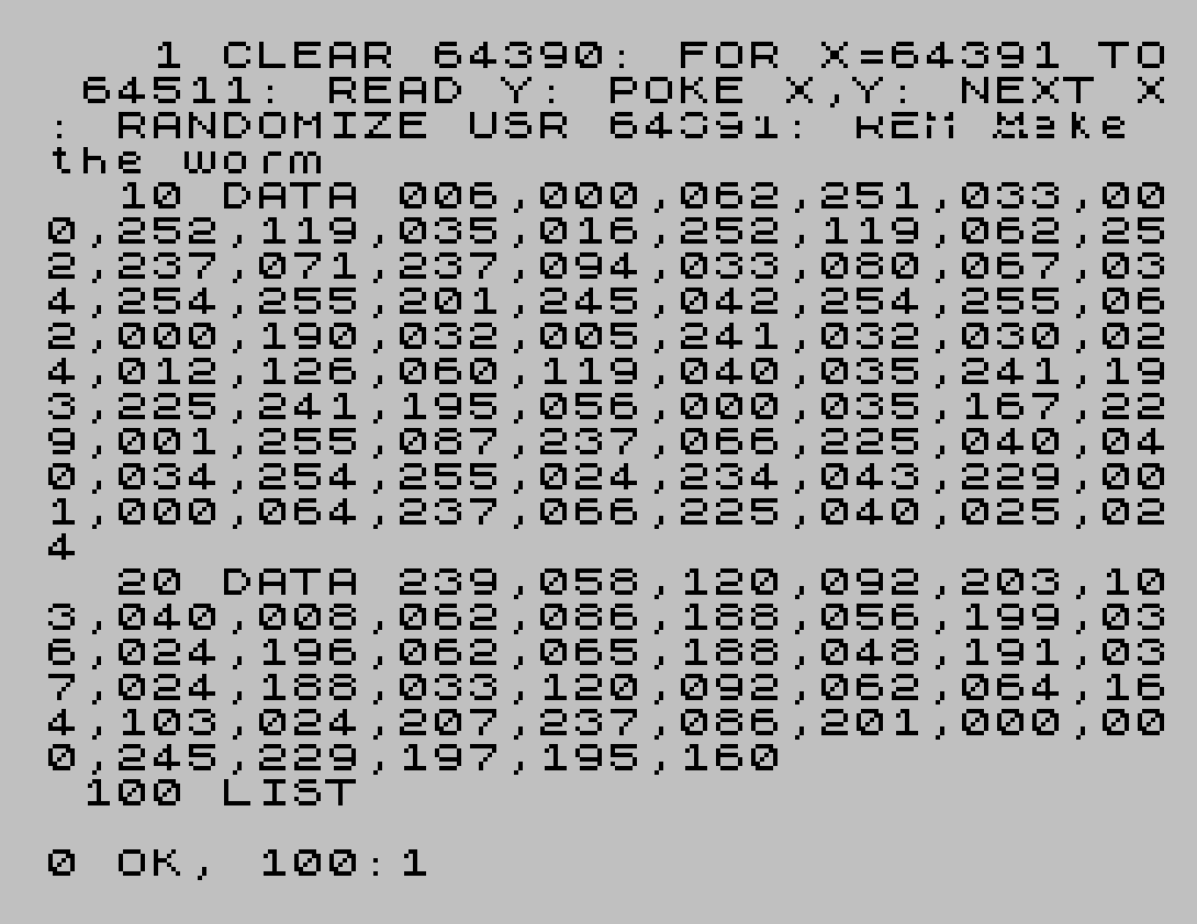
    1 CLEAR 64390: FOR X=64391 TO 64511: READ Y: POKE X,Y: NEXT X: RANDOMIZE USR 64391: REM Make the worm
   10 DATA 006,000,062,251,033,000,252,119,035,016,252,119,062,252,237,071,237,094,033,080,067,034,254,255,201,245,042,254,255,062,000,190,032,005,241,032,030,024,012,126,060,119,040,035,241,193,225,241,195,056,000,035,167,229,001,255,087,237,066,225,040,040,034,254,255,024,234,043,229,001,000,064,237,066,225,040,025,024
   20 DATA 239,058,120,092,203,103,040,008,062,086,188,056,199,036,024,196,062,065,188,048,191,037,024,188,033,120,092,062,064,164,103,024,207,237,086,201,000,000,245,229,197,195,160
  100 LIST
Note: Type-in program listings on this website use ZMAKEBAS notation for graphics characters.