
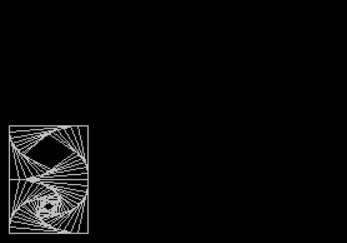
This program draws three successive animated fractal-like geometric figures using an iterative corner-cutting (Chaikin-style) algorithm, then loops continuously. Each section initializes a set of control points and repeatedly replaces them with weighted interpolations between adjacent vertices — parameterized by `SU` (step ratio) and `RU = 1 – SU` — drawing the evolving polygon at each iteration with PLOT and DRAW. The first section renders a 4×4 grid of quadrilateral spirals with alternating vertex orientations; the second draws a triangular grid pattern with sign-flipped coordinates to create a diamond-like arrangement; the third generates a hexagonal grid. Between each section, `RANDOMIZE USR 50450` is called (likely a ROM routine or machine code entry point for a screen effect), followed by a PAUSE and CLS before the next figure begins.
Program Structure
The program is divided into four logical blocks, separated by PAUSE, CLS, and a final GO TO 1 that creates an infinite loop:
- Lines 1–120: Setup and first figure — a 4×4 grid of quadrilateral (4-point) iterative spirals.
- Lines 210–330: Second figure — a triangular (3-point) grid arranged in a diamond/chevron pattern with sign-alternating offsets.
- Lines 410–530: Third figure — a hexagonal (6-point) grid drawn across a 3×3 arrangement.
- Line 540:
GO TO 1restarts the entire sequence.
Each section shares the same core algorithmic pattern: initialize control points into arrays X() and Y(), then iterate a corner-cutting loop that draws the current polygon and updates the vertices.
Corner-Cutting Algorithm
The geometric engine is a variant of the Chaikin corner-cutting algorithm. At each iteration, every vertex M is replaced by a weighted average of itself and the next vertex NJ:
T(M) = RU * X(M) + SU * X(NJ)K(M) = RU * Y(M) + SU * Y(NJ)
The ratio SU controls how aggressively the corners are cut. Values used are 0.12 (section 1), 0.1 (section 2), and 0.2 (section 3). After each iteration the polygon is drawn before the points are updated, producing a visual spiral as the shape converges inward toward a smooth curve.
Wrap-around indexing for the “next vertex” uses the modulo idiom: NJ = INT(M - N * INT(M/N)) + 1, where N is the number of vertices (4, 3, or 6 depending on section). This avoids an explicit IF branch for the wrap.
Section 1 — Quadrilateral Grid (Lines 10–120)
A 4×4 grid is formed by double-nested FOR I=0 TO 3 / FOR J=0 TO 3 loops. The parity of I and J (computed via INT(I - 2*INT(I/2)), i.e., I MOD 2) determines which of two Y-coordinate configurations is used, creating alternating orientations that tile the screen. Each cell draws 19 iterations (N=0 TO 18) of the 4-point spiral.
Section 2 — Triangular Grid (Lines 210–310)
This section is the most complex. It uses variables II and JJ (toggling between −1 and 1) to alternate the vertical direction of each triangle, producing a diamond/chevron tiling. A guard condition IF I<J OR I>4-J THEN GO TO 310 skips cells outside a triangular region of the 5×4 grid, giving an overall diamond outline. The color index C cycles through values 1–3 (using modulo-3 arithmetic) to change the ink color of successive triangles, though the PLOT/DRAW calls do not explicitly set INK attributes here — C is computed but not visibly applied via INK C, making this a likely artifact of the IBM-to-TS-2068 conversion.
Section 3 — Hexagonal Grid (Lines 410–510)
Six control points define a regular hexagon, and an offset E (0 or 31) is applied when I=1 to vertically stagger the middle column, producing a honeycomb-like offset grid. The loop iterates 21 times (N=0 TO 20) per cell. Coordinate scaling by factors of 0.8 (X) and 0.9 (Y) maps the hexagons to the screen dimensions with a slight horizontal compression. A guard IF J=0 AND I<>1 THEN GO TO 510 suppresses cells in the first row except the center, shaping the overall pattern.
Machine Code Call
Each section ends with RANDOMIZE USR 50450. Address 50450 is outside the normal BASIC area and points to machine code — likely a screen transition or flash effect injected into RAM or the system area. The use of RANDOMIZE USR rather than a BASIC subroutine call indicates a deliberate low-level hook, possibly producing an animated wipe or color fill between figures.
Key BASIC Idioms
- Modulo via INT:
INT(X - N * INT(X/N))used throughout for wrap-around indexing and parity checks, since the ZX BASIC dialect lacks aMODoperator. - Double-buffered arrays: Temporary arrays
T()andK()hold updated vertex positions while the originals are still being read, then copied back — essential for correct simultaneous update. - Single-pass draw: The innermost loop draws the polygon edge before updating points, so each of the N iterations renders a visible polygon, creating the spiral effect with no separate display step needed.
Potential Anomalies
- In section 2, the variable
Cis incremented and modulo-cycled but never used in anINKorPAPERstatement. This strongly suggests the original IBM program used color commands that were not fully translated in the conversion. - The
DRAWin line 280 uses(X2-X1)and((Y2-30)-(Y1-30))— the subtraction of 30 from both Y values cancels out, making this equivalent to(Y2-Y1). This is a harmless redundancy, likely a transcription artifact. - Array dimensions
DIM X(6)etc. at line 10 allocate 6 elements, sufficient for all three sections (max 6 vertices in section 3), so no out-of-bounds access occurs even in sections using fewer vertices.
Image Gallery
Source Code
   1 BORDER 0:PAPER 0:INK 7:CLS
   5 REM CONVERTED FROM IBM TO TS-2068 BY TED KNYSZEK
  10 DIM X(6):DIM Y(6):DIM T(6):DIM K(6)
  20 LET SU=.12:LET RU=1-SU
  30 FOR I=0 TO 3:FOR J=0 TO 3:IF INT (I-2* INT (I/2))= INT (J-2* INT (J/2)) THEN GO TO 50
  40 LET Y(1)=43:LET Y(2)=0:LET Y(3)=0:LET Y(4)=43:GO TO 60
  50 LET Y(1)=0:LET Y(2)=43:LET Y(3)=43:LET Y(4)=0
  60 LET X(1)=1:LET X(2)=1:LET X(3)=64:LET X(4)=64
  70 FOR N=0 TO 18:LET X1=X(4)+I*63:LET Y1=Y(4)+J*43
  80 FOR M=1 TO 4:LET X2=X(M)+I*63:LET Y2=Y(M)+J*43
  90 PLOT X1,Y1:DRAW (X2-X1),(Y2-Y1):LET X1=X2:LET Y1=Y2:LET NJ= INT (M-4* INT (M/4))+1
 100 LET T(M)=RU*X(M)+SU*X(NJ):LET K(M)=RU*Y(M)+SU*Y(NJ):NEXT M
 110 FOR P=1 TO 4:LET X(P)=T(P):LET Y(P)=K(P):NEXT P:NEXT N:NEXT J:NEXT I
 115 RANDOMIZE USR 50450
 120 PAUSE 300
 130 CLS
 210 LET SU=.1:LET RU=1-SU:LET II=1:LET C=1
 220 FOR J=0 TO 3:LET II=-II:LET JJ=1:FOR I=0 TO 4:LET JJ=-JJ:IF I<J OR I>4-J THEN GO TO 310
 230 IF J<2 OR I>2 THEN LET C=(C- INT (C/3)*3)+1
 240 IF J=3 THEN LET C=(C- INT (C/3)*3)+1
 250 LET X(1)=0:LET X(2)=39:LET X(3)=78:LET Y(1)=0:LET Y(2)=-48:LET Y(3)=0:IF II=JJ THEN LET Y(2)=48
 260 FOR N=1 TO 11:LET X1=3+X(3)+I*39:LET Y1=160-Y(3)-J*48+II*JJ*24
 270 FOR M=1 TO 3:LET X2=3+X(M)+I*39:LET Y2=160-Y(M)-J*48+II*JJ*24:LET C=(C- INT (C/3)*3)+1
 280 PLOT X1,Y1-39:DRAW (X2-X1),((Y2-30)-(Y1-30)):LET X1=X2:LET Y1=Y2:LET NJ=(M- INT (M/3)*3)+1
 290 LET T(M)=RU*X(M)+SU*X(NJ):LET K(M)=RU*Y(M)+SU*Y(NJ):NEXT M
 300 FOR P=1 TO 3:LET X(P)=T(P):LET Y(P)=K(P):NEXT P:NEXT N
 310 NEXT I:NEXT J
 315 RANDOMIZE USR 50450
 320 PAUSE 300
 330 CLS
 410 LET SU=.2:LET RU=1-SU
 420 FOR J=0 TO 2:FOR I=0 TO 2:IF J=0 AND I <>1 THEN GO TO 510
 430 LET E=0:IF I=1 THEN LET E=31
 440 LET X(1)=0:LET X(2)=25:LET X(3)=75:LET X(4)=100:LET X(5)=75:LET X(6)=25
 450 LET Y(1)=31:LET Y(2)=0:LET Y(3)=0:LET Y(4)=31:LET Y(5)=62:LET Y(6)=62
 460 FOR N=0 TO 20:LET X1=25+(X(6)+I*75)*.8:LET Y1=(220-Y(6)-J*62-E)*.9
 470 FOR M=1 TO 6:LET X2=25+(X(M)+I*75)*.8:LET Y2=(220-Y(M)-J*62-E)*.9
 480 PLOT X1,Y1:DRAW X2-X1,Y2-Y1:LET X1=X2:LET Y1=Y2:LET NJ= INT (M-6* INT (M/6))+1
 490 LET T(M)=RU*X(M)+SU*X(NJ):LET K(M)=RU*Y(M)+SU*Y(NJ):NEXT M
 500 FOR P=1 TO 6:LET X(P)=T(P):LET Y(P)=K(P):NEXT P:NEXT N
 510 NEXT I:NEXT J
 515 RANDOMIZE USR 50450
 520 PAUSE 300
 530 CLS
 540 GO TO 1
Note: Type-in program listings on this website use ZMAKEBAS notation for graphics characters.