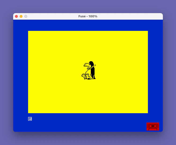
Draws Opus the Penguin, the character from Bloom County.
This program renders a detailed graphic image of Opus the Penguin, the character from Bloom County, using 20 user-defined graphics (UDGs) characters arranged in a 4×5 tile grid. It loads UDG slots starting at character code 144 (UDG “a” through “t”) by POKEing 8 bytes of bitmap data per character, read sequentially from DATA statements, terminating on the sentinel value 256. The display is constructed at screen position row 8, column 14, printing four UDG characters per row across five rows to assemble the full composite image. A yellow paper (PAPER 6), blue border (BORDER 1), and black ink (INK 0) color scheme frames the graphic. The program was centered and color-enhanced by Anthony Willing on 2/4/89, based on an original listing from TS Horizons.
Program Analysis
Program Structure
The program divides into three logical phases: UDG loading (lines 1–35), DATA tables (lines 100–600), and display plus housekeeping (lines 1000–1020). The loading loop reads all 20 UDGs sequentially, and the display section prints the completed tile mosaic.
- Initialization (lines 2–5): Sets screen colors and initializes
x=144, the ASCII code of the first UDG slot (“a”). - UDG loading loop (lines 10–35): Reads 8 bytes per character, POKEs them into UDG bitmap RAM, then advances to the next UDG.
- DATA tables (lines 100–600): Twenty groups of 8 bytes each, terminated by a sentinel value of
256at line 600. - Display (line 1000): Prints the 20 UDGs as a 4-wide × 5-tall tile grid.
- Termination (lines 1010–1020):
STOPhalts execution;SAVE "Opus" LINE 1saves with auto-run.
UDG Loading Mechanism
The outer control variable x starts at 144 and is incremented at line 35 after each group of 8 bytes, stepping through UDG slots \a (144) through \t (163). The inner FOR n=0 TO 7 loop reads one byte per iteration and POKEs it to USR CHR$ x+n. This idiom exploits the fact that USR CHR$ x returns the address of the 8-byte bitmap for character code x, so adding n offsets to successive bytes within that definition.
Termination is handled by a sentinel: when READ r returns 256 (an impossible pixel byte value), line 15 redirects execution to line 1000 rather than continuing to POKE.
Data Tables
The DATA is organized in groups of four 8-byte rows per hundred-line block, corresponding to the four columns of UDGs in each tile row. The layout maps to the display as follows:
| DATA block | UDGs defined | Display row |
|---|---|---|
| 100–130 | \a \b \c \d | Row 1 (PRINT AT 8,14) |
| 200–230 | \e \f \g \h | Row 2 (PRINT AT 9,14) |
| 300–330 | \i \j \k \l | Row 3 (PRINT AT 10,14) |
| 400–430 | \m \n \o \p | Row 4 (PRINT AT 11,14) |
| 500–530 | \q \r \s \t | Row 5 (PRINT AT 12,14) |
Line 510 contains only 7 data values rather than 8, which means the sentinel at line 600 is read one iteration early during the loading of UDG \r. This is a bug: UDG \r will only have 7 of its 8 bytes POKEd before the sentinel triggers a jump to line 1000, leaving the last byte of that UDG at whatever value it previously held in RAM. Depending on the machine’s memory state, the bottom row of that tile may display incorrectly.
Key BASIC Idioms
POKE USR CHR$ x+n, r— usesUSRwith a string argument to obtain the bitmap address for a given character code, a standard UDG-definition technique.- Sentinel-terminated DATA — using an out-of-range value (256) to signal the end of data avoids needing to hard-code the UDG count.
LET x=x+1: GO TO 10at line 35 re-enters the FOR loop from its header, effectively implementing a nested loop without a secondFOR/NEXTconstruct.PRINT AT r,c;with concatenated UDG escape sequences assembles the multi-tile graphic in a single statement per row.
Display and Color
The composite image occupies rows 8–12, columns 14–17 — a 4×5 character block near the horizontal center of the 32-column display. The yellow paper (PAPER 6), blue border (BORDER 1), and black ink (INK 0) combination was explicitly added by the credited contributor, Anthony Willing, distinguishing it from the monochrome original published in TS Horizons.
Notable Anomaly
As noted above, line 510 contains only 7 data values (80,88,72,36,152,152,255) instead of the required 8. Because the sentinel value 256 at line 600 immediately follows, the loop reads it as the eighth byte of UDG \r, triggering the IF r=256 THEN GO TO 1000 branch mid-POKE. The final byte of UDG \r is never written, and UDGs \s and \t (which the DATA at lines 520–530 was intended to define) are never loaded at all. This means the bottom two rows of UDGs displayed in PRINT AT 12,14 will show whatever bitmaps happen to reside in those UDG slots from a previous run or system default.
Content
Image Gallery
Source Code
    1 REM "opus"  (listing from  TS HORIZONS -- centered, color  added by Anthony Willing 2/4/89)
    2 PAPER 6
    3 CLS : BORDER 1: PAPER 6: INK 0
    5 LET x=144
   10 FOR n=0 TO 7
   15 READ r: IF r=256 THEN GO TO 1000
   20 POKE USR CHR$ x+n,r
   30 NEXT n
   35 LET x=x+1: GO TO 10
  100 DATA 0,0,0,0,0,0,0,0
  110 DATA 0,0,0,0,0,63,64,64
  120 DATA 0,15,31,63,31,95,95,31
  130 DATA 0,128,192,224,224,240,240,240
  200 DATA 0,1,1,1,0,0,0,0
  210 DATA 144,144,0,255,0,0,1,2
  220 DATA 55,3,3,161,67,35,70,189
  230 DATA 249,249,233,192,152,56,120,252
  300 DATA 0,0,0,0,0,0,0,0
  310 DATA 2,2,1,0,1,2,4,8
  320 DATA 161,191,99,131,3,3,3,3
  330 DATA 252,252,252,252,252,252,252,252
  400 DATA 0,0,0,2,13,20,18,40
  410 DATA 16,16,32,34,221,101,106,96
  420 DATA 3,3,3,131,69,69,69,69
  430 DATA 252,252,252,252,252,252,248,244
  500 DATA 32,28,2,1,1,0,0,0
  510 DATA 80,88,72,36,152,152,255
  520 DATA 129,129,177,72,8,16,224,255
  530 DATA 244,236,236,236,236,110,15,255
  600 DATA 256
 1000 PRINT AT 8,14;"\a\b\c\d": PRINT AT 9,14;"\e\f\g\h": PRINT AT 10,14;"\i\j\k\l": PRINT AT 11,14;"\m\n\o\p": PRINT AT 12,14;"\q\r\s\t"
 1010 STOP
 1020 SAVE "Opus" LINE 1
Note: Type-in program listings on this website use ZMAKEBAS notation for graphics characters.