PCB Aid generates a printer-ready dot-matrix grid template for designing printed circuit boards, scaled to a user-specified length in inches. The program first defines five custom UDG characters (at addresses UDG “a” through UDG “e”) by POKEing eight bytes each into UDG RAM, using patterns such as solid vertical lines (63, 252), a dot-grid pattern (36,0 repeating), and a connector-hole motif (0,60,0,0…). A scaled loop outputs the grid using LPRINT: the top and bottom edges use a border string built from UDG “a”, “b”, “c”, and “d”, while interior rows use blank lines interspersed with periodic edge-hole rows using UDG “e” at every eighth row. The program also draws a decorative screen diagram of a PCB edge connector using PLOT and DRAW commands before prompting for the board length.
Program Analysis
Program Structure
The program is divided into three logical phases: a graphical title screen drawn with PLOT/DRAW (line 5), a UDG initialization loop (lines 10–135), and the interactive LPRINT output phase (lines 140–240). Line 300 is defined but unreachable in normal execution — it appears to be a leftover or dead code fragment.
UDG Initialization
Lines 10–60 form a loop that reads 8-byte rows from DATA statements and POKEs them into UDG memory starting at USR "a" (char 144). The variable x is used as a numeric offset so that POKE USR CHR$ x+n, r writes each byte into the correct UDG slot. A sentinel value of 256 (line 135) terminates the READ loop and redirects execution to line 140.
The five UDGs defined are:
| UDG | Char | Pattern bytes | Visual description |
|---|---|---|---|
| \a | 144 | 60×8 | Centered vertical stripe (4 pixels wide) |
| \b | 145 | 63×8 | Right-heavy horizontal fill (bottom 6 bits) |
| \c | 146 | 252×8 | Left-heavy horizontal fill (top 6 bits) |
| \d | 147 | 36,0 repeating | Dot-grid / pin-hole pattern |
| \e | 148 | 0,60,0,0,0,0,60,0 | Connector-hole motif (horizontal bars at rows 2 and 7) |
String Construction for LPRINT
Line 140 builds t$ as a 32-character string of UDG “a” with one UDG “d” at position 6, representing a top/bottom PCB rail with a slot marker. Line 150 copies t$ to b$, then line 160 uses a string slice assignment — b$(7 TO 8)="\b\c" — to embed UDGs “b” and “c” at positions 7–8, creating a corner/slot variant for the board edges. Line 165 builds e$ as 32 repetitions of UDG “e” to represent a row of connector holes across the board width.
Scaled Output Loop
Line 180 computes the total number of interior LPRINT rows as lt = 16*l - 4, where l is the board length in inches. The factor of 16 converts inches to printer rows at 16 lines per inch (matching standard 0.1-inch grid pitch), minus 4 rows reserved for the two top and two bottom border lines. The loop at lines 200–220 emits a blank LPRINT for each row, but inserts a full row of UDG “e” connector holes at n = l*8 - 2, placing them at the half-length point of the board. The top border (b$, twice) and bottom border (t$, twice) are output outside the loop.
Title Screen Graphics
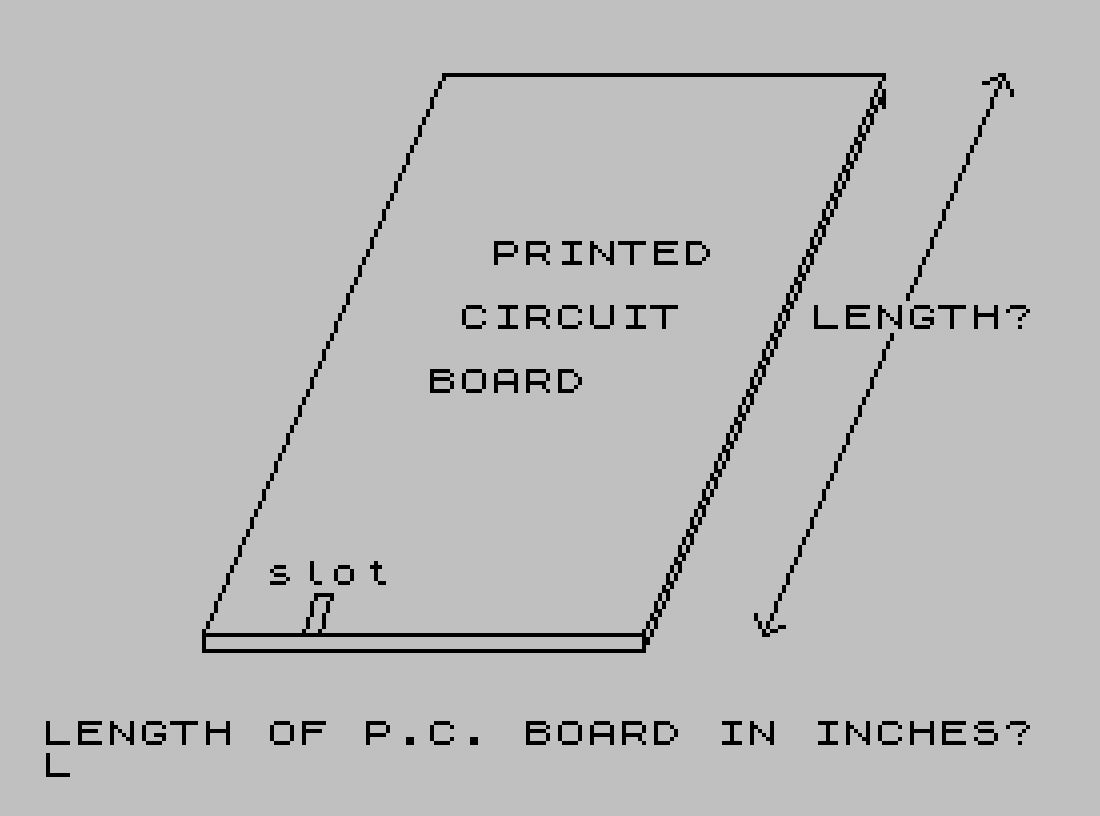
Line 5 draws a stylized PCB edge connector diagram using a series of PLOT and DRAW commands. The main board outline is a closed trapezoid; additional DRAW sequences add detail lines suggesting the card-edge connector teeth and notch cutouts. The PRINT AT statements in line 7 overlay text labels (“PRINTED CIRCUIT BOARD”, “slot”) and use FLASH 1 to highlight the “LENGTH?” prompt.
Notable Techniques
- The sentinel value
256in the DATA stream is an elegant way to terminate a UDG loading loop without needing a separate counter or EOF check. - String slice assignment (
b$(7 TO 8)="\b\c") efficiently creates a variant of a string without rebuilding the entire string. - The
PAUSE 4E4(approximately 27 minutes at 50 Hz) at line176functions as a “press any key” wait using scientific notation for the large constant. - Line
300(LPRINT e$: GO TO 220) is unreachable dead code; it may be a vestige of an earlier design where it was called viaGO SUBor a different conditional branch. - The program appears twice in the listing — this is a duplication artifact in the source, not two separate programs.
Potential Anomalies
The connector-hole row is printed only once, at the midpoint of the board (n = l*8 - 2). For a standard dual-row edge connector, one would expect two such rows near each end; the current logic places a single row near the center, which may not accurately represent a real PCB edge connector layout. Additionally, line 300 is dead code that will never execute in the normal flow from line 240 (STOP).
Content
Image Gallery
Source Code
    5 CLS : PLOT 40,20: DRAW 110,0: DRAW 60,140: DRAW -110,0: DRAW -60,-140: DRAW 0,-4: DRAW 110,0: PLOT 150,20: DRAW 0,-4: DRAW 60,140: DRAW 0,-4: PLOT 65,20: DRAW 3,10: DRAW 4,0: DRAW -3,-10: PLOT 180,20: DRAW 60,140: PLOT 178,25: DRAW 2,-5: DRAW 5,2: PLOT 235,158: DRAW 5,2: DRAW 2,-5
    7 PRINT AT 7,14;"PRINTED";AT 9,13;"CIRCUIT";AT 11,12;"BOARD";AT 17,7;"slot";AT 9,24; FLASH 1;"LENGTH?"; FLASH 0
   10 LET x=144
   20 FOR n=0 TO 7
   30 READ r: IF r=256 THEN GO TO 140
   40 POKE USR CHR$ x+n,r
   50 NEXT n
   60 LET x=x+1: GO TO 20
  100 DATA 60,60,60,60,60,60,60,60
  110 DATA 63,63,63,63,63,63,63,63
  120 DATA 252,252,252,252,252,252,252,252
  130 DATA 36,0,36,0,36,0,36,0
  132 DATA 0,60,0,0,0,0,60,0
  135 DATA 256
  140 LET t$="\a\a\a\a\a\d\a\a\a\a\a\a\a\a\a\a\a\a\a\a\a\a\a\a\a\a\a\a\a\a\a\a"
  150 LET b$=t$
  160 LET b$(7 TO 8)="\b\c"
  165 LET e$="\e\e\e\e\e\e\e\e\e\e\e\e\e\e\e\e\e\e\e\e\e\e\e\e\e\e\e\e\e\e\e\e"
  170 INPUT "LENGTH OF P.C. BOARD IN INCHES?"'l
  175 CLS : PRINT AT 8,6;"TURN PRINTER ON AND";AT 11,3;"PRESS ANY KEY TO CONTINUE"
  176 PAUSE 4E4: CLS
  180 LET lt=16*l-4
  190 LPRINT b$: LPRINT b$
  200 FOR n=1 TO lt
  205 LPRINT
  210 IF n=l*8-2 THEN LPRINT e$
  220 NEXT n
  230 LPRINT t$: LPRINT t$
  240 STOP
  300 LPRINT e$: GO TO 220
Note: Type-in program listings on this website use ZMAKEBAS notation for graphics characters.