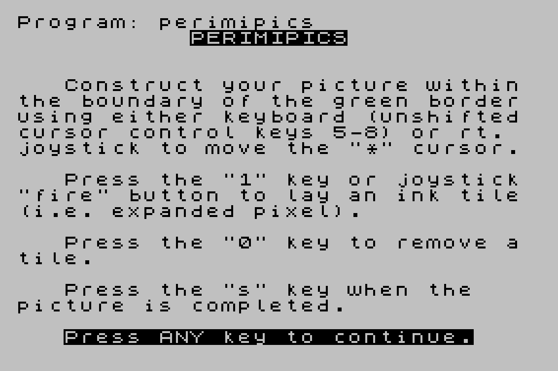
Perimipics is a drawing program that lets the user move a cursor around a bordered canvas using keyboard keys 5–8 or a joystick, placing or removing filled block-graphic tiles to compose a picture. When the drawing is complete, the program converts the 22×24-cell canvas into nine user-defined graphics (UDGs A through I), each storing a portion of the image as POKEd character data at addresses 65368–65416. A companion subroutine at line 9987 reassembles and displays the nine UDGs as a tiled image on screen, and the instructions explain how to preserve or merge the UDG data with other programs using NEW, DELETE, or MERGE commands.
Entry for the SyncWare News programming contest.
Program Analysis
Program Structure
The program divides into four logical phases:
- Initialization (lines 1–30): Builds a 528-character string
A$representing the canvas, displays instructions, and waits for a keypress. - Drawing loop (lines 40–190): Draws a green border, then enters a real-time loop reading input (joystick via machine code or keyboard), updating cursor position, and placing or removing tiles in
A$. - UDG generation (lines 191–313): Iterates over the canvas string and POKEs computed byte values into the nine UDG slots, then prints post-processing instructions and stops.
- Display subroutine (lines 9986–9999): Reassembles the nine UDGs into a full-screen picture using tiled PRINT AT statements.
Canvas Representation
The canvas is encoded as a 528-character string A$ (lines 10–17). Line 10 creates a 32-character space string; line 15 multiplies it ninefold to 288 characters, and line 17 doubles it again. The result is a flat array of 528 characters indexed by a single position counter SC, where each character is either a space (empty) or the block graphic \:: (filled). The canvas is 24 columns wide and 22 rows tall (24×22 = 528).
Cursor Movement and Input Handling
The main loop uses a dual input path. If no key is pressed (line 60), it calls a machine code routine at address 26720 via RANDOMIZE USR 26720 (line 61), which reads joystick state and returns delta values via PEEKs at addresses starting at X (26715). If a key is pressed, line 70 reads the keyboard scan code from system variable address 23560 into P, and line 80 updates the scalar cursor position SC using Boolean arithmetic: (P=56) moves right, (P=54) moves up by a row (adds 24), (P=53) moves left, and (P=55) moves down.
The joystick path (lines 61–62) extracts directional and fire information from four consecutive PEEKed bytes relative to address X, accumulating movement into SC and storing the fire state in W. Lines 90–100 clamp SC to the range 0–527 to keep the cursor within bounds.
Tile Placement
The cursor is displayed by printing "*" at the computed row and column (line 140), then immediately overprinted with the current canvas cell content from A$ (line 150), giving a flicker effect. Line 160 sets the canvas cell to a filled block graphic \:: if joystick fire (W=1) or the "1" key is pressed. Line 170 clears the cell on "0". The brief PAUSE 3 delays on lines 140 and 150 control the cursor blink rate.
UDG Generation
Lines 205–300 convert the canvas into nine UDGs (A through I). The outer loop steps through UDG memory addresses 65368 to 65416 in steps of 24 (8 bytes × 3 columns per UDG). For each UDG, nested loops iterate over 8 rows (C) and 3 byte-columns (R). The innermost loop (lines 240–280) reads eight consecutive canvas cells and assembles a byte by treating each filled cell as a 1-bit, summing M * 2^H where M is 1 if the cell equals \::. The assembled byte is POKEd into the appropriate UDG address at line 290.
| UDG | Canvas columns | Canvas rows |
|---|---|---|
| A | 0–7 | 0–7 |
| B | 8–15 | 0–7 |
| C | 16–23 | 0–7 |
| D | 0–7 | 8–15 |
| E | 8–15 | 8–15 |
| F | 16–23 | 8–15 |
| G | 0–7 | 16–21 (+pad) |
| H | 8–15 | 16–21 (+pad) |
| I | 16–23 | 16–21 (+pad) |
Display Subroutine (lines 9987–9999)
The subroutine at line 9987 tiles the nine UDGs across the screen. Lines 9988–9991 print the left and right border columns (C=0 and C=29) for each set of three rows. Lines 9992–9998 handle the top and bottom rows: the first pass covers columns 3–12, the second (triggered when M≠17) covers columns 17–26, filling the interior of the screen with the assembled UDG picture. The inner subroutine at line 9999 prints a 3×3 block of UDGs A–I using a single PRINT AT statement with three lines.
Notable Techniques
- String
A$used as a flat 2D canvas array, indexed by a single scalarSCdecomposed into row/column with integer division. - Boolean expressions cast to integers (0 or 1) for arithmetic updates to
SC, avoiding IF branches in the movement logic. - Machine code joystick driver called via
RANDOMIZE USR, with results communicated back through PEEKed memory locations. - Bit-packing loop using powers of two (
2^H) to serialize canvas cells into UDG bytes without bitwise operators. - The program is designed to be partially preserved after completion: the UDG data and display subroutine survive a
NEWcommand and can be merged into user programs.
Potential Anomalies
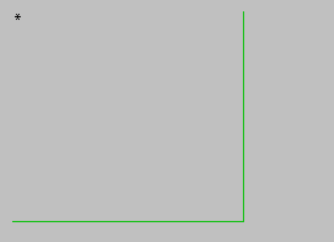
The INK 4: PLOT 0,0: DRAW 192,0: DRAW 0,175: INK 0 sequence at line 40 draws only two sides of the border (bottom and right), relying on the screen edge for the other two sides rather than completing a full rectangle. Also, PAUSE 4E4 at line 30 uses floating-point scientific notation for the pause duration, which is an unusual but valid idiom to express a large frame count without typing all digits.
Content
Image Gallery
Source Code
    1 REM ![hq#> GO SUB x+ THEN RESET  6+ THEN G 6+ THEN O 6+ THEN W 6+ THEN _USR 6<>
   10 LET A$="                                "
   15 LET A$=A$+A$+A$+A$+A$+A$+A$+A$+A$
   17 LET A$=A$+A$
   20 LET SC=0: LET X=26715
   25 PRINT AT 2,11;"PERIMIPICS";AT 5,3;"Construct your picture withinthe boundary of the green borderusing either keyboard (unshiftedcursor control keys 5-8) or rt. joystick to move the ""*"" cursor.";'';"   Press the ""1"" key or joystick""fire"" button to lay an ink tile(i.e. expanded pixel).";'';"   Press the ""0"" key to remove atile.";'';"   Press the ""s"" key when the   picture is completed.";'';"   Press ANY key to continue."
   30 PAUSE 4E4: CLS
   40 INK 4: PLOT 0,0: DRAW 192,0: DRAW 0,175: INK 0
   55 PRINT AT 0,0;"*"
   60 IF INKEY$<>"" THEN GO TO 69
   61 RANDOMIZE USR 26720
   62 LET SC=SC+PEEK X+24*PEEK (X+2)-PEEK (X+1)-24*PEEK (X+3): LET W=PEEK (X+4)
   63 GO TO 90
   69 LET W=0
   70 LET P=PEEK 23560
   80 LET SC=SC+(P=56)+24*(P=54)-(P=53)-24*(P=55)
   90 IF SC<0 THEN LET SC=0
  100 IF SC>527 THEN LET SC=527
  110 LET V=INT (SC/24)
  120 LET H=SC-24*V
  130 LET Z$="*"
  140 PAUSE 3: PRINT AT V,H;Z$
  150 PAUSE 3: PRINT AT V,H;A$(SC+1)
  160 IF W=1 OR INKEY$="1" THEN LET A$(SC+1)="\::"
  170 IF INKEY$="0" THEN LET A$(SC+1)=" "
  190 IF INKEY$<>"s" THEN GO TO 60
  191 CLS : PRINT FLASH 1;AT 5,12;"STAND BY"; FLASH 0;AT 8,7;"Graphic characters";AT 9,6;"are being generated.";AT 15,5;"The computer will BEEP when";';"finished - your picture will be stored in graphic characters A-I"
  200 LET N=1
  205 FOR O=65368 TO 65416 STEP 24
  210 FOR C=0 TO 7
  220 FOR R=0 TO 2
  230 LET B=0
  240 FOR H=7 TO 0 STEP -1
  250 LET M=(A$(N)="\::")
  260 LET B=B+M*2^H
  270 LET N=N+1
  280 NEXT H
  290 POKE (O+R*8+C),B
  300 NEXT R: NEXT C: NEXT O
  302 BEEP .25,12: BEEP 1,12
  310 CLS
  312 PRINT AT 2,4;"You may now:";'';TAB 6;"*Use the ""NEW"" command -";';TAB 7;"the graphic characters";';TAB 7;"will be preserved.";'';TAB 6;"*Use the ""DELETE  ,313""";';TAB 7;"command to remove the";';TAB 7;"utility program - the";';TAB 7;"border subroutine and";';TAB 7;"graphic characters are";';TAB 7;"available to ""MERGE""";';TAB 7;"with your own program.";'';TAB 6;"*Use the ""GOSUB 9987"" com-";';TAB 7;"mand to display your";';TAB 7;"PERIMIPICS to the screen.";'';TAB 6;"*Use the ""RUN"" command";';TAB 7;"to start over."
  313 STOP
 9986 REM *PERIMIPICS subroutine*
 9987 CLS
 9988 FOR C=0 TO 29 STEP 29
 9989 FOR R=0 TO 18 STEP 3
 9990 GO SUB 9999
 9991 NEXT R: NEXT C
 9992 LET M=3: LET N=12
 9993 FOR R=0 TO 18 STEP 18
 9994 FOR C=M TO N STEP 3
 9995 GO SUB 9999
 9996 NEXT C: NEXT R
 9997 IF M=17 THEN RETURN
 9998 LET M=17: LET N=26: GO TO 9993
 9999 PRINT AT R,C;"\a\b\c";AT R+1,C;"\d\e\f";AT R+2,C;"\g\h\i": RETURN
Note: Type-in program listings on this website use ZMAKEBAS notation for graphics characters.