
From my own personal experience, information gleaned from various articles in the Timex-Sinclair field of literature and comments from Bill Jones (TDM), it is clear that the method of powering the 2068 (i.e. the use of a switching regulator for the development of the regulated 5 volt bus from the 15-20 volt unregulated supply) has serious problems. This method has merit if the computer is to be used in a mobile application where operation would be from a 12 volt battery supply as it can supply the necessary 5 volt bus at a far greater efficiency than the alternative LM-309K/7805K regulators. However, for the more conventional computer uses, where operating power is not a restriction, and several peripheral devices are to be used, this method leads to the following problems:
1) Production of back-ground noise and critical cassette SAVE/LOAD operations, especially when the regulated 5 volt bus is heavily loaded with peripherals;
2) Noise induction from Switching Regulator to Data lines;
3) Limited regulated 5 volt supply at rear edge connector;
4) Possible 5 volt bus voltage spikes;
5) Excessive heating of the computer after prolonged usage;
6) A proliferation of transformers and power cords for all of the necessary peripherals.
Of the foregoing, Item 3 is by far the most devastating. With severe loading of the 5 volt bus by add-on peripherals, the switching regulator blows and puts 6-9 volts DC ripple on this line, blowing the RAM chips of the computer, the number of chips destroyed depending on how quickly the power can be turned off.
I have measured the power consumption of various 2068s and peripherals with the following results:
Device                5 volt load        12 volt load

2068                  510 ma               60 ma
A & J MicroDrive      100 ma             10/170 ma
JL Oliger Ptr/IF       20 ma
JL Oliger D-D/IF      300 ma
OS-64 cartridge        25 ma idle, to 100 ma active
2764 EPROM in Dock     20 ma idle, to 100 ma active
27128 EPROM in Dock    25 ma idle, to 100 ma active
Bill Jones says that, to his knowledge, the AERCO D-D/IF is one of the worst power hogs, but he did not provide its actual power consumption. It may be assumed that any memory expansion boards will draw significant amounts of power. Disk drives draw considerable power, but this is normally supplied by a dedicated power supply. My TANDON 55D-4s each draw 250 ma @ 5 volts and 480/850 ma @ 12 volts. The 3.5″ drives draw much less.
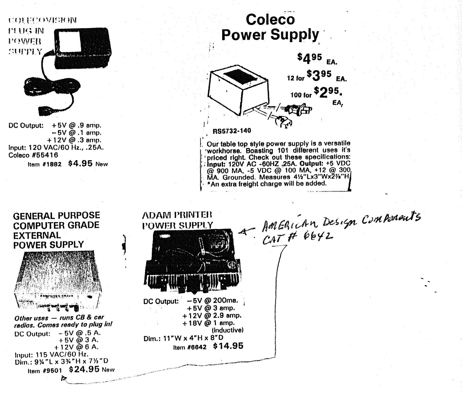
The problem of the 5 volt bus loading can be solved by cutting the 5 volt Vcc trace of “the first add-on device”. Then splice in, on the out-board side of that trace, +5 volts from an auxiliary supply. There are several individual power supplies available which will provide a regulated 5 volts at about 1 Amp. A COLECO power supply is available from Edlie Electronics, their catalog # RS5732-140, and from American Design Components, their catalog # 1882, outputs of +5V @ .9A, -5V @ .1A, +12V @ .3A, $4.95 plus shipping. Whatever supply is used, the output must be regulated between +5.25V and +4.75V. This solution will add to the proliferation of power cords, however, and does nothing to resolve the noise problems associated with the switching regulator circuit.
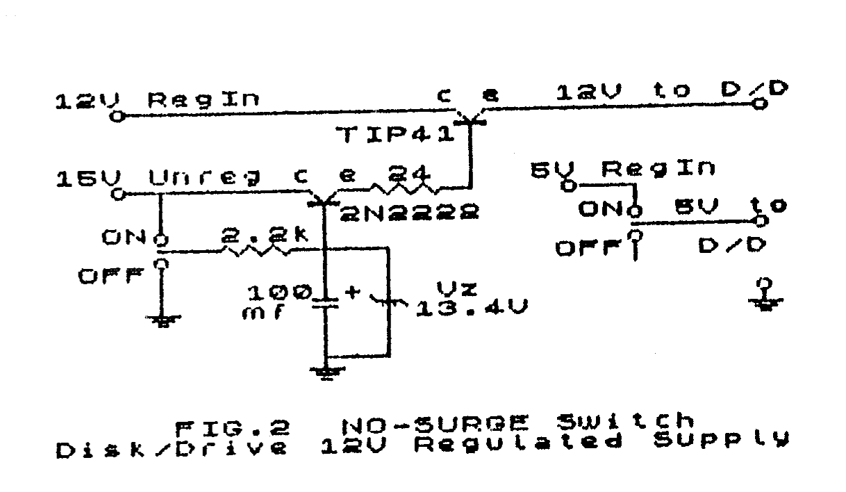
My solution to these problems is to provide a husky (5V 3A, 12V 3A, and 18VAC 1A) linear (rather than switching) power supply to power the 2068 computer, 2040 printer, A&J MicroDrive and Oliger Printer Interface and Disk Interface as well as the two 5.25″ disk drives. One unit appropriate for this use is a general purpose computer grade external power supply, outputs of -5V @ .5A, +5V @ 3A and +12V @ 6A, American Design Components catalog #9501 @ $24.95. This unit comes in a very presentable enclosed cabinet and should have sufficient space for the addition of necessary switches and sockets. If a disk drive power supply is already in use, it might be readily adaptable to this task (refer to figures 1 and 2).
The unit I selected for this task is the COLECO ADAM Printer Power Supply, American Design Components catalog #6642 @ $14.95, also available at various electronic surplus stores (Any other unit of similar characteristics could be used). This item comes exposed on a metal frame from which it was removed and installed in an enclosed metal box (3.5″ x 6″ x 10″) with one side cut out to clear the heat sink. On one end of the box I installed a 3 pin CB microphone jack for computer power, a 3 pin miniature Molex socket for D/D power and a coaxial DC power jack for the 2040 printer power. On the opposite end I installed a DPDT switch for the D/D 12V and 5V supplies and a SPST switch for the 2040 printer 18VAC supply. The computer power, 12V unregulated (about 20 volts) and 5V regulated, is unswitched, as is the power unit itself, these being controlled from a switched power socket. A paragraph at the end of this article will discuss the switching for the D/D power.
The modifications to the computer, which disables the switching regulator, are as follows (refer to component placement chart):
1) Remove the power jack J1;
2) Remove Power transistor Q1- D43C1;
3) Remove diode CR1- 1N5821;
4) Remove resistors R1- .110 ohm 3W (blue ceramic, brown-brown-silver), R2- 68 ohm .2W (blue-grey-black), R4- 330 ohm .5W (orange-orange-brown), R5- 3.32 kohm .2W (orange-orange-red-brown-brown), R6- 1.10 kohm .2W (brown-brown-black-brown-brown), R9- 62 kohm .2W (blue-red-orange);
5) Remove capacitors C36- 1000pf (.001K100 green MYLAR), C37- .1mf (CGW 104 Z5J green tubular), C59- 120pf (121 ceramic disc)
Locate pin 5 of the switching regulator, U1- uA78S40. Using very small snips, cut it at the PC board, bend up from the board and jumper it to the + lead of C41- 47uf 16V. Run the power lead (I used a 6 conductor, 3 leads for ground, 2 leads for 5V regulated and 1 lead for 12V unregulated) through the Power hole in the case. Connect the ground lead(s) to the front pad where power jack J1 was removed. Connect the 12V lead to the rear pad where J1 was removed. Connect the 5V lead(s) to the pad where the cathode of CR1 was removed. Double check and Triple check to insure that the 5V lead goes to the cathode pad of CR1, otherwise ALL of the computer chips may FRY!!! While the computer case is open, and since the computer can no longer be RESET with the power switch, a SPST NO push button switch should be mounted on the back panel of the computer in line with the SCLD chip and connected to pins 26 and 29 of U19, Z80A-CPU; and C21, 1uf 16V, located between U14 and U9, should be replaced with a 5 to 10 uf 16V capacitor to provide more reliable reset on turn-on.
Now for the Disk Drive power switching mentioned earlier. The bane of all Disk Drives is the corruption of disks when the disk drive power is activated with a disk in the drive (it happens to the most experienced of us). This corruption is caused by the current surge/voltage spike created by the instantaneous application of power to the inductive load of the motors in the drive. I have found that if the 12V is applied to the drive in an exponential ramp rather than square wave, there is no current surge/voltage spike generated, thus no disk corruption. Figures 1 and 2 show how this is achieved by the charge/discharge curve of the 100uf capacitor and 2.2kohm resistor in the base circuit of the 2N2222 transistor. The circuit switches the 5V instantaneously and the 12V with an exponential rise.


American Design Components
62 Joseph Street
Moonatchie, NJ 07074
800-524-0809
Edlie Electronics
2700 Hempstead TPKE.
Levittown, NY 11756
800-645-4722
Editor’s note: While Jim’s total change out of the TS-2068 power supply is a very worth while project, a cheap and alternate solution is to buy one of the small Coleco power packs and splice in to the “first add-on” device normally used in your TS-2068 system. It is essential that the +5 V trace from the computer is cut in order to isolate the two voltage regulators for each other. POWER ON sequence would be to first turn on the external supply, and then the computer. There are other possibilities for thought. Since the aux power is separate from the TS-2068, a simple additional circuit could be added to supply REFRESH voltage to any external RAM, thus making the RAM Non-volatile (Memory that does not forget). Then one could just leave the external power supply ON to keep the data that may be contained in external RAM. UPDATE has not tested any of the External Power applications presented, but the theory is sound, and the existing problem is real.
Another alternative is to use the External Power circuit given by Charles Bothner in his continuing articles about EXTRA MEMORY. This one has been tested (by Charles), but that power supply involves “home put-together” on a proto board.
Symptom of overload are: A ‘fairly warm’ spot on the top case of the computer; jumpy screen; Have to occasionally OFF and back ON to get Copyright display; Trouble loading from cassette “programs the you have SAVED”. The fact that “we have been operating for years” with an overloaded TS-2068 voltage regulator means two things. 1. The amazing capability of the voltage regulator to exceed its rated output. 2. The luck of the Irish in getting away with it. In my case TWO failures have been experienced. The first resulted in the frying of all TS-2068 RAM chips. Ole Dan Elliott came to the rescue and fixed both computers. I wonder how many “Former TS-2068 users” have been attritted due to Voltage regulator failures. I believe they number in the tens of thousands. Thanks Jim, for a good analysis of the subject. Ed.