
No one wants to be called simple, or cheap. Yet where engineering solutions are concerned,both of these things are virtues of immeasurable value. The method described here is the cheapest and simplest emulator yet, if we don’t count merely swapping ROMs inside the TS2068. Among methods that allow switching between the Spectrum and TS2068 modes, its definitely the simplest and cheapest, and I think it’s also the best. Still, that last statement may be debated, depending on what you prefer.
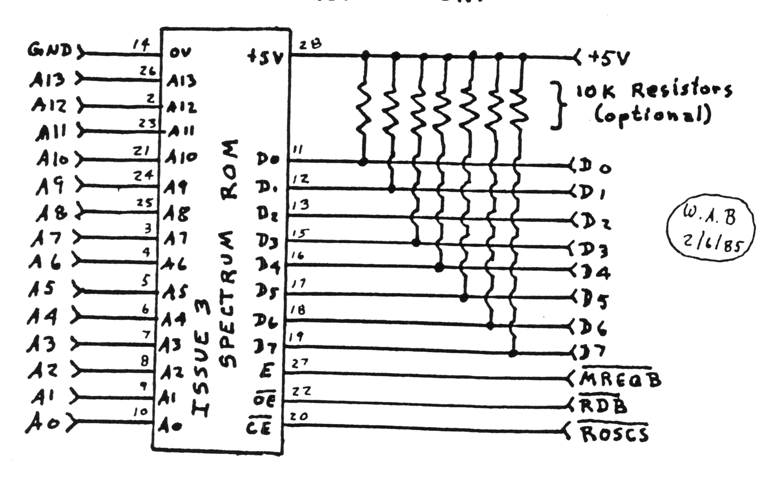
In the October 1984 issue of SINCUS NEWS, I proposed a method of producing a cartridge based emulator that used a Spectrum ROM, where mode switching is performed through software. Doug Dewey of the Triangle Sinclair User’s Group, was the first to actually try this method out, and he’s redesigned his emulator to accomdate it. I suspect that the majority of readers prefer programming to soldering; no one has damaged their TS2068 with a bad program after all. For these people, I’d recommend you contact Doug for details on his product. Nevertheless, for those who’d like to “roll their own”, I’ve provided instructions to do just that — requiring no electronic components except one Spectrum ROM !
This further simplification of my emulator method means that less wiring will be required. Such a feature will be especially useful to those just starting out in building electronic projects. For those who don’t mind things being a little more complicated, the optional seven resistors make the TS2068 act a little more like a Spectrum. ( The TS2068 does weird things to the data bus when there’s no hardware writing to it, while the Spectrum, puts an FF there. Those with access to a real Spectrum can try PRINT IN 0 on both computers, to see the difference. ) I have actually seen software in which these resistors matter. Certain software methods using interrupt mode 2 form a prime example.
Those with some technical knowledge of the TS2068 may have a few questions about this method. I’ll try to anwser some of the more likely ones here.
First, the code in locations 0001-0004 of a Spectrum ROM does not follow the format specified for the cartridge memory in the TS2068 technical manual. Actually, this is very fortunate. If we walk through the initialization code where the cartridge memory is checked, we see that if the “standard” format is not followed the computer simply assumes that no cartridge is present and continues on. Thus turned on, it “wakes up” as a TS2068. Because of this, we can use software to switch back and forth. If the standard format were followed, it would not be possible to switch from the Spectrum to the TS2068 mode without some sophisticated machine code.
Second, as shown, the Spectrum ROM is not uniquely mapped into the computer’s memory. That is, it is mapped simultaneously into the 0-16, 16-32, 32-48 and 48-64K blocks of memory. However, in normal use, only chunks 0 and 1 of the cartridge bank will be enabled, and so the TS2068 itself performs the additional mapping, so that the ROM occupies only the 0-16K area, as it should.
There is evidence that Timex intended to do this in it’s own cartridges. Cartridges could have been either AROS, starting at location 8000. The byte at location 0001 should be 01 to identify an LROS, and the byte at 8001 should be 02 to identify a LROS. In either case, this is the second-to-the-lowest byte of of ROM memory. Note that the format could have been simplified by using 01 to identify either, but this would not have been so if the ROM were mapped into multiple blocks. The difference between the two I.D. bytes is probably intended to tell the TS2068 where it should “map” the ROM, by enabling the appropriate cartridge bank chunks. By also locating decoupling capacitors right next to the cartridge connector, Timex ensured that a program that could fit on one ROM would require only one ROM on a board, and nothing more. (Programs requiring two ROMs would have required a third mapping chip.)
I expect that it’s not just a happy coincidence that the standard ROM configuration includes three “low true” enabling lines, and that to enable the cartridge ROM we must simultaneously have a active “low true” signals; MREQB, RDB, and ROSCS. Unfortunately the standard EPROM has only two “low true” enabling lines, so this one chip method won’t apply to EPROMS.
A third possible question may relate to the lack of a pullup resistor on D2. If we review the TS2068 schematic, we see that D2, and only D2 already has a 10K pullup resistor; we don’t ne[illegible] to add one here. This is probably used during the system initialization, when the TS2068 is building the system configuration tables, and is searching for the expansion banks that Timex never produced (poor dumb machine !) A ROM bank is identified by bit 2=0 in a certain location. A missing bank would have bit 2=1 due to the pullup resistor. Since no other pullups appear necessary, Timex didn’t include them.
A last question may relate to the lines of BASIC next to the schematic. They’re intended to be entered in the immediate mode; don’t try to put line numbers on them and SAVE them. Such a cassette switch won’t work. If you want a cassette switch, you can use this program instead:
  10 CLEAR 39999
  20 DATA 175,24,2,62,3,243,211,
244,199
  30 FOR j=40000 TO 40008: READ
 a: POKE j,a: NEXT j
  40 PRINT "Press S for Spectrum
": PRINT "Press T for TS2068": B
EEP .1,11
  50 IF INKEY$="S" OR INKEY$="s"
 THEN RANDOMIZE USR 40003
  60 IF INKEY$="T" OR INKEY$="t"
 THEN RANDOMIZE USR 40000
  70 GO TO 50
You may find the “cassette switch” useful when you’re getting started, but you’ll quickly find the lines of BASIC by the schmatic to be easier.
The OUT 244, commands switch the Spectrum ROM in and out of memory, causing a system crash. The RANDOMIZE USR 0 commands initialize the system, allowing a “controlled crash” from which the system can recover, with the newly switched in ROM. This method is about as elegant as lobster with catsup, but it works beautifully, and is perfectly “legal”.
That’s about it. Those with additional questions can write to me
Wes Brzozowski
[address omitted]
Please enclose a SASE for a reply. The truly anxious can call me at [phone number omitted]. Please DO NOT call collect. Please DO NOT call after 10pm Eastern time. I’ll be glad to answer any questions.
NOTE: My articles are never bear any copyrights. I design and write bcause I enjoy it. Anyone wishing to manufacture and sell this item is free to do so, but I’d appreciate you’re sending me one or two of the finished item as a courtesy. Have Fun !
TS2068 TO SPECTRUM:
     RANDOMIZE USR 0
     OUT 244, 3
     RANDOMIZE USR 0

SPECTRUM TO TS2068:
     RANDOMIZE USR 0
     OUT 244, 0
       - when you get a [K]
         cursor, press ENTER.
         The computer will
         honk at you. Then:
     RANDOMIZE USR 0

(NOTE: The system will re-initialize
  after every RANDOMIZE USR 0)
Note: Type-in program listings on this website use ZMAKEBAS notation for graphics characters.