
Dear INTERFACE,
One cannot really complain of the limitations of the ZX81 computer at such a snip of a price, but one drawback seems to be the keyboard. This is a layered plastic and metal film composition which is sensitive to small pressure of the finger, and the only real way of knowing if you have pressed the key in the right place, or with sufficient pressure is to constantly look up at the TV screen.
The circuit shown causes an audible ‘beep’ every time a key is successfully pressed, thus alleviating neckache.
The circuit is snall enough to fit inside the case of the ZX81 just underneath the keyboard and is powered from the computers 5V rail. The addition of this circuit in no way interferes with any of the operations of the ZX81.
A commercial version of this idea is on the market and costs over £10. The circuit described should cost no more than about £1.50.
Circuit Description
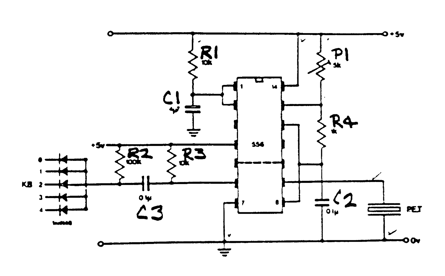
The circuit is based on the 556 dual timer chip with one of the timers being used in a monostable mode of approx 50mS and the other being used as an astable to drive the piezo electric transducer. The circuit may be trimmed to obtain the resonant frequency of the transducer.
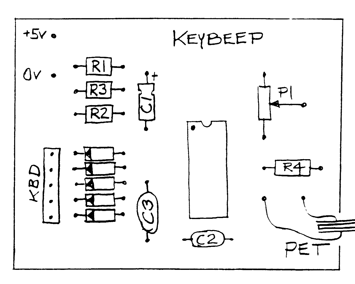
KEYBEEP PARTS LIST
R1   10K  1/4 watt resistor
R2   100K       "
R3   10K        "
R4   1K         "
C1   4.7uF, 10v Electrolytic
C2   0.1uF, polyester
C3   0.1uF, polyester
P1   5K Trimpot
D1-5 1N4148 Signal Diode
IC1  LM556 Dual Timer
KBD  5pin connector
PET  Piezo Electric
       Transducer
Article reprinted from ZX Appeal
Artwork by Rene Bruneau