
Hardware Relief from Crashes
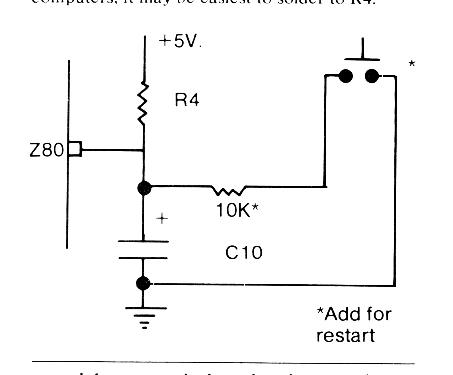
After many a POKE where I should not have been POKEing, the ritual of unplugging the ZX80 to restart became a chore. It may seem silly, but there may be some PEEKing and POKEing programmers who do not know that a reset pin exists on the Z80 microprocessor. After several bouts with crashed programs I gave in and placed a push button switch and resistor as shown in the drawing on my ZX80. Since I drive my monitor directly I had removed the modulator long ago and put the bright red button nicely in the RF out hole. Now when programs fall into the black hole of endless, breakless loops, I press the big red, and relief is milli-seconds away.
High Contrast Inverse Resolution
One disappointment I had with the ZX80 was the compromise which had to be made between resolution of inverse video characters and the contrast or sharpness of the screen. I drive a cheap tube TV set directly as a monitor and the only way to maintain readability of the cursor was to set the contrast low. The following idea helped eliminate some of that problem and opened new graphics potentials.
By placing a 5K resistor and diode between the video out (before the modulator at the junction of R30, 32) and pin 4 of IC-20 (see drawing below and schematic as published in SYNC 1:1) everytime an inverse character is printed a small amount of white is added to it thus lifting the inverse video out of the soup even in high contrast situations. An added bonus is that inverses are no longer exactly inverse. Graphics now have a pleasant variety of four shades of grey. The effect on some graphics is the illusion of depth or texture. Another feature is that this resistor/diode can also be used to probe the timing of events within the display field by terminating the diode at various points within the computer instead of at the pin mentioned above. A variety of masks, field patterns (mostly from the refresh cycle), and other video goodies exists within. One mask in particular, if shifted four clock cycles later, shades the text thus aiding readability. Another blocks out the main graphics area whether or not the field is occupied. The smaller the resistor’s value the blacker the masks and patterns become. If too small, however, a crash is possible. The greatest use to me of this mode has been is unlocking event timing within the ZX80.
