Ed.- A WORD OF CAUTION: Any hardware project for your computer must be approached with extreme caution. SYNC cannot be responsible for any problem that may arise from attempting hardware projects. Obviously, any damage to your computer can be costly in time and money.
Strong KBD Signals Again
Stephen G. Turner
The Hardware Tips in SYNC 2:4 regarding strong signals on KBD 0 to KBD 4 came at a time when I had some missing shifted functions so I decided to try the solution. However, I did not want to attempt to remove RP3 which would probably involve crushing the pack and unsoldering the wires one at a time. Instead, using the formula
Rt = 8.6K = R1 R2 / (R1 + R2)
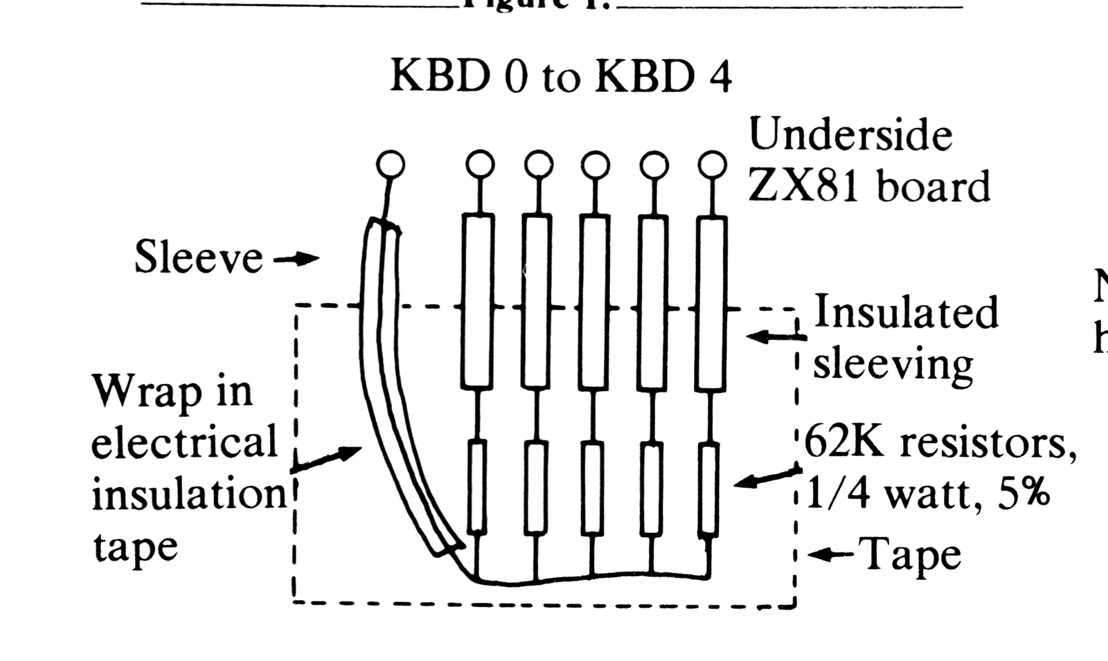
where R1 is the resistor pack value, I decided to wire parallel 62K = R2 resistors on the underside of the board as shown in Figure 1.
All of my keyboard functions now work. So Herb Hornung has a right answer.
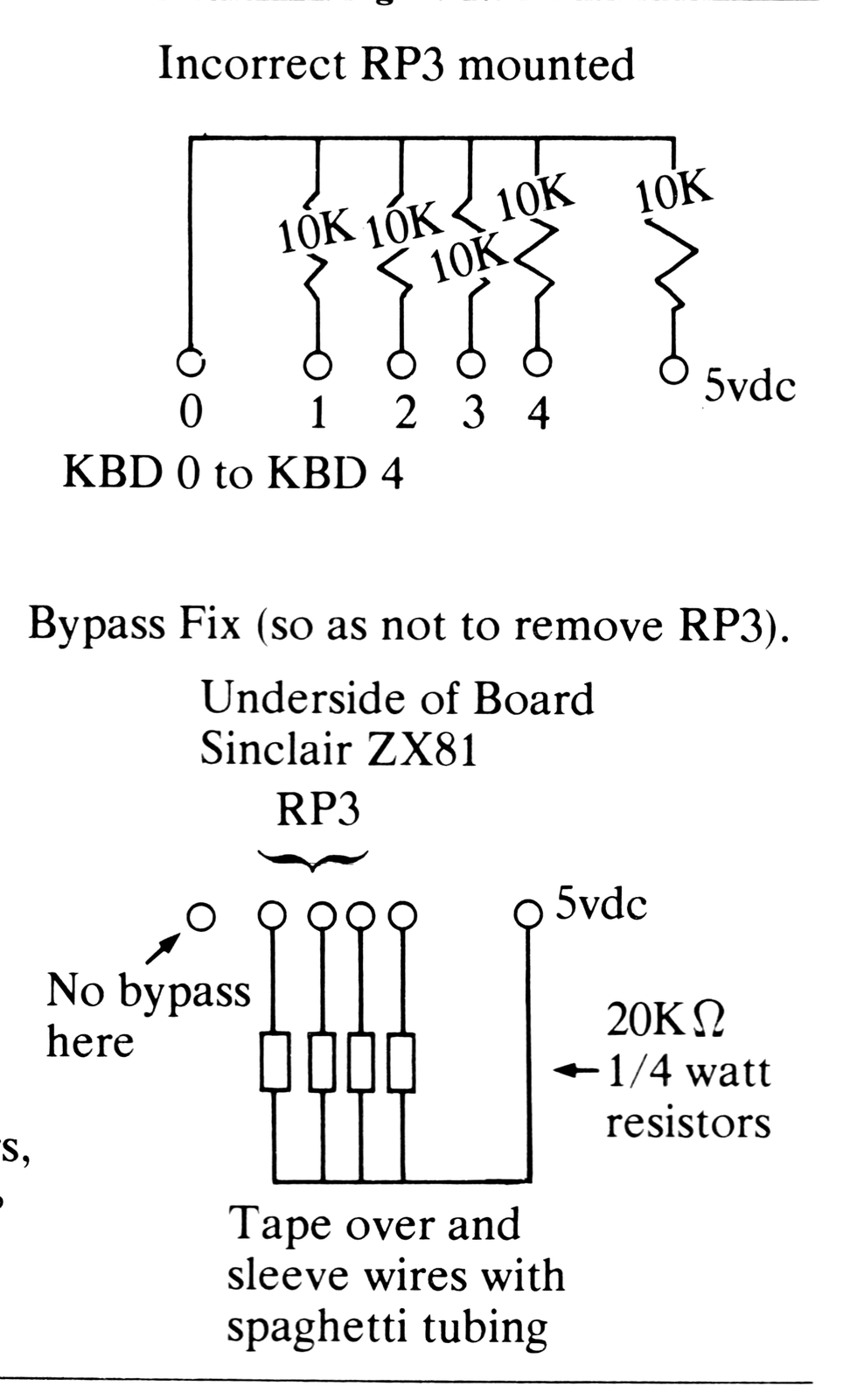
A further aspect of the problem involves the RP3 itself. Through correspondence with Sinclair, I found that the RP3 may be installed backwards. This would cause 20K instead of 10K to be at four of the five keyboard connectors. This would cause many of the upper case functions not to work. The correct orientation of the RP3 pack is with the lettering away from the keyboard connectors.
You can solve this problem in either of two ways. 1) Remove the RP3 and install a new one in the correct direction (with the lettering away from the connectors). 2) Use the underside of the board to parallel the four positions of high resistance with 20K resistors. See Figure 2.
I also learned that the incorrect installation of the RP1 (the correct orientation is with the lettering toward the Z80A) will cause the 16K RAM pack not to work. This is the same case only with RP1 installed backwards.
Overheating Problems
Stephen G. Turner
My ZX81 with 16K RAM suffers the heating problems typical of this combination: disappearing cursor, total crash (loss of video), “wait state” (keyboard will not respond); and blurry display. Generally, at any of these states, the 7805 heat sink could toast muffins.
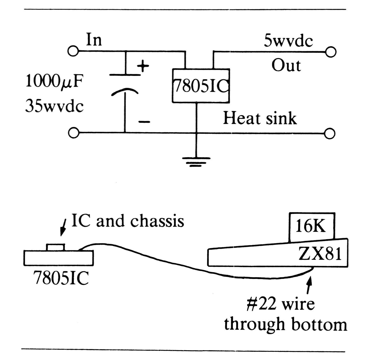
My solution was to remove the 7805IC and to mount it externally on a chassis box with a 1000uF, 35wvdc cap on the input side to clear up the screen interference. I used #22 wires from the chassis box through the ZX81 grill holes to the IC connecting points. This solved the problems.
Users of the Sinclair will have to be realistic that overheating is a culprit of system failures. Since the Sinclair is a tremendous unit for the price, it is worth fixing the heating problem.
RAM Expansion Problems
Tom Keeney
ZX80 owners attempting to upgrade their computer memory past address location 32767 may have display problems unless they make a circuit modification. The problem becomes apparent when RAMTOP is moved past the 32K boundary and will manifest itself by the presence of black dots in the screen margins. Those who have installed MicroAce Video Upgrades will get a special treat: the dots will actually move across the margins in an orderly fashion, like a drill team of ants! This will happen anytime a key is pressed or during any computation.
The problem is caused by the fact that the contents of the data bus are sometimes shifted into the video when addresses above 32767 are accessed.
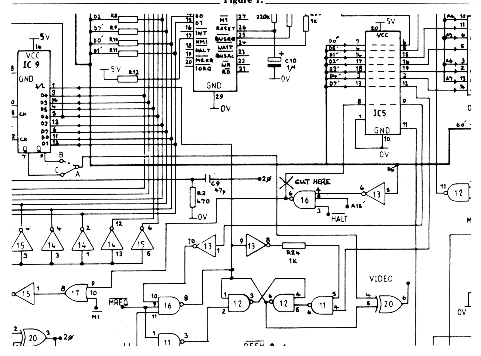
The cure is to add the M1 (instruction fetch) condition to the video shift signal generation logic. As indicated in Figure 1, this is done by cutting the board trace between IC5 pin 8 and IC16 pin 6 and installing a jumper between IC5 pin 8 and IC17 pin 8. Care should be exercised in making the board cut because it is easy to accidentally cut the connection between IC16 and IC17.