
Our previous I/O hardware article described an output device addressed like memory. This month, we’ll capture data through a port, placing it into a CPU register.
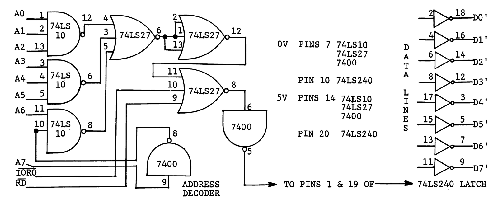
Your ZX80 or MicroAce uses a Z80 CPU chip that can address 256 ports, one-byte locations through which you can transfer data in or out of the ZX80. You simply need a tri-state gate and an address decoder. When the appropriate address appears, the decoder signals the gate to connect external data with D0′-D7′ lines of the Z80 bus via the 46-pin connector at the rear of your ZX80.
Port and memory addresses differ, but the same number can refer to a memory location or a port. Your machine uses control lines MREQ and IORQ to tell one from another.
While the CPU requires 16 bits to access memory locations, Z80 chips use only 8 bits to address ports. Just AND the desired combination of A0-A7 with IORQ and RD. When this combination comes up on the bus, the external buffer connects the outside data to D0′-D7′. Signals on the bus don’t conflict because input instructions that send IORQ tell the CPU to read the bus rather than to control it. After the allotted time, IORQ disappears, and the external device loses its connection with the bus.
You use a simple machine language program, called from BASIC with a USR statement, to read the port and bring data into your program from other devices.
4K ADDRESS     HEX        OPCODE
 43FAh         DB7F       IN A, (127)
 43FC          2600       LD H, 0
 43FE          6F         LD L, A
 43FF          C9         RETURN
DECIMAL:  219  127  38  0  111  201
  (POKE origin at 17402)

8K ADDRESS     HEX        OPCODE
 43FAh         DB7F       IN A, (127)
 43FC          0600       LD B, 0
 43FE          4F         LD C, A
 43FF          C9         RETURN
DECIMAL:  219  127  6  0  79  201
  (POKE origin at 17402)
Before loading the USR routine, you must reserve RAM space. For 4K machines, see PLACING USR CALLS (Jun. 81,p.8); if you have an 8K machine, you can move RAMTOP down:
POKE 16388, 250
POKE 16389, 67
NEW (NL)
You can also assign data to an array in a FOR-NEXT loop. This way you can both read and store data simultaneously.
Because the ROM uses some ports for display and tape operations, not all are available to us. We used port number 127, but you might want to explore other odd-numbered ports.
You can use bits of the port one at a time, or the entire byte can represent a character. Thus, the 8 bits could read 8 switches on doors throughout your building or two BCD digits from a digital voltmeter. In fact, you can pack information into the byte any way you want–unscramble it with a program once it’s in the machine.
ZX80 PORTS USED IN 8K ROM
IN:  221, 232, 254
OUT:  253, 255
BOTH IN AND OUT:  251 and 254