
For those of you with a standard ZX81 /Timex-Sinclair 1000, this article may not be of much interest since, without any peripheral devices, your computer will transmit a clear video display with most TVs. However, if you have added an external keyboard, a motherboard, or even just a 16K RAM pack you will probably have encountered those annoying little bands of interference that just will not go away, regardless of how much you reposition your computer or fiddle with the fine tuning. The problem arises from the square waves generated by all digital circuitry which are picked up very nicely at 63 MHz (you guessed it—channel 3). Shielding all components will do much to alleviate the situation, but the hard-core computer hack with motherboards, modems, and meters of wire-wrap may find it difficult or undesirable to put all that circuitry under aluminum. Also, shielding does not usually eliminate the problem entirely, as those with a ZX81 and 16K RAM alone will probably attest—the video quality is much better without the RAM pack plugged in.
A solution that is relatively inexpensive, easy to do, and (best of all) permanent, regardless of how much extra hardware you have, is to convert your ZX/TS to transmit over UHF channel 33 (146 MHz). At that frequency those nasty little digital spectral (Fourier) components go virtually undetected. It is interesting to note that European ZX81’s come with a UHF-33 modulator instead of the VHF 2,3 found in the American model.
So if you are willing to invest about $15, a half hour of your time, and do not mind invading the inner sanctum of your computer (which will void the warranty of a factory assembled unit), then read on.
If you consult chapter 25 of ZX81 Basic Programming, you will find a nice photograph of the ZX81 hardware layout. (I assume there is a similar photo in the T/S 1000 programming book also.) The VHF video modulator is the small silver box in the upper left corner of the circuit board. (If you have a sharp eye, you will notice that the modulator in the photograph is a UHF modulator.) In this project all we need to do is replace this with a UHF channel 33 modulator. These are currently available from: Computer Continuum, 301 16th Ave., San Francisco, CA. 94118 (cost $15 ppd. with instructions, as of this writing). You may be able to find one for less at some discount electronics houses if you want to shop around a bit.
Once you get your channel 33 modulator get a 15-25 watt soldering iron, some rosin-core solder, a small Phillips-head screwdriver, and a pair of needle-nose pliers. Follow the steps below for interference free video!
1) Assemble all your materials in a clean, well-lit work area.
2) Remove the circuit board from your computer by removing the five Phillips-head screws from the back cover. Three of these screws are located under the little rubber pads at the corners. Note that the two screws at the front corners are shorter than the back three screws. Inside you will see two short screws holding the circuit board to the front cover. Remove these, carefully noting their exact location on the board (important when you reassemble). Carefully disconnect the keyboard leads by gently pulling them free. Be careful not to tear or kink these leads or you will have big problems later on.
3) Locate the modulator (see the photo in chapter 25) and disconnect the three leads from its lower end by heating the solder pads with your iron and pulling them free with the needle-nose pliers. Be careful not to pull too hard or you may damage the printed circuit traces on the board.
4) At this point the modulator is being held down by two solder lugs located on its underside at each end. Heat these from beneath the board and pull them free one end at a time. You may have to work it free a little bit at a time, heating one end then the other.
5) With the modulator removed you should be able to see printed markings on the circuit board, as noted in Figure 1 (e.g., Fr 3, UK 2, etc.). Note that there are only two leads on the UHF modulator, one protruding from a little insulator (Figure 2). Push the solder lugs of the UHF modulator into the holes one at a time while heating. You will notice that the jack for the TV cable is closer to the EAR jack than on the other modulator. Add extra solder to the lugs if needed, since these are the ground connections and should be secure.
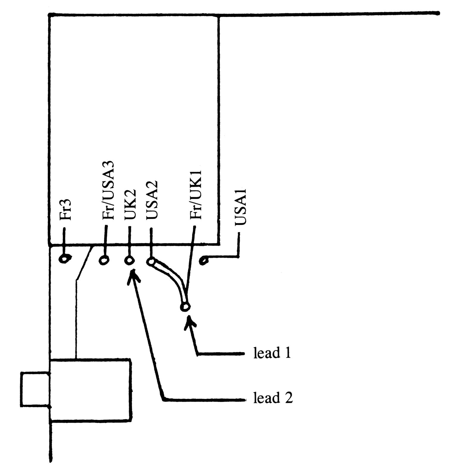
6) Consulting the figures and the circuit board markings (which I hope you read before you soldered the modulator down over them), solder the lead from the insulator (lead 1) into the hole at the end of the line marked “Fr/UK 1”. This is the 5V power source. Be sure to pull the lead through the board and trim any excess wire to prevent shorts.
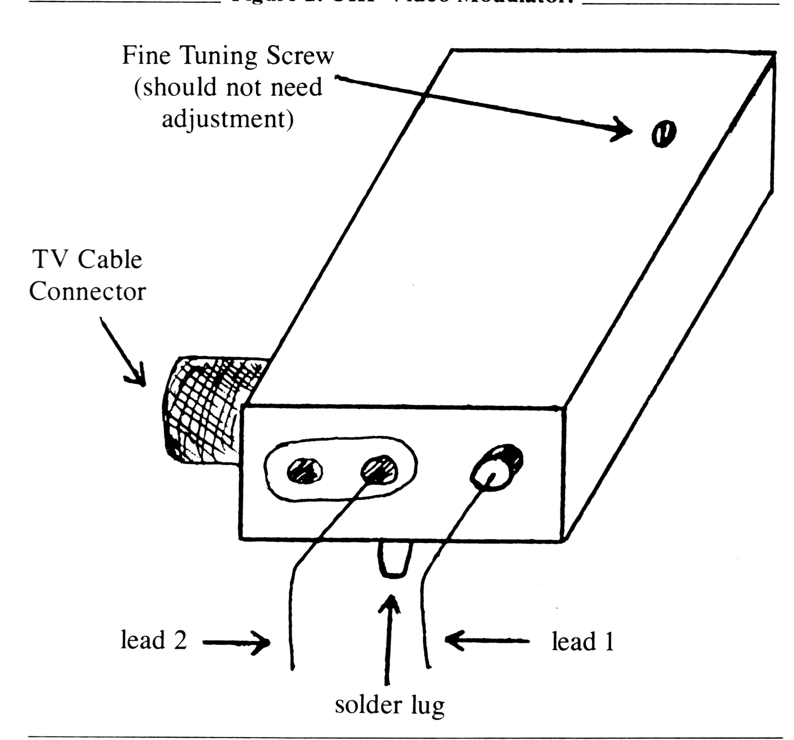
7) Solder lead 2 into the hole marked “UK 2” (Figure 1). This is the video signal from pin 16 of the Sinclair Computer Logic IC.
8) Make sure there are no shorts between the leads you have soldered and any of the printed circuit traces on the board (check both sides). Also be sure your solder joints are good at the leads and the solder lugs.
9) Now it is a good idea to see if the thing works before putting it back in its case. Plug the TV cable into the modulator, reposition the two leads from the antenna switch box to the UHF leads of your TV, turn to UHF channel 33, and plug in your power supply. You should see a nice, clear blank screen with the “K” cursor in the lower left corner, even without the keyboard hooked up. If you do not, fine tune your UHF tuner on the TV, recheck your modulator connections (is lead 2 in the right hole?), look for shorts, etc.
10) Before you can put your computer back together you have to cut a new hole in the side of the front cover to accommodate the different position of the TV cable jack. Use the mold marks already on the case (used with the European ZX’s) as a guide. A piece of stiff wire wrapped around the tip of your soldering iron can be used to heat-cut a hole very easily.
11) Plug the keyboard tails into the sockets on the circuit board and carefully reposition it onto the mounting posts on the front cover. The keyboard tails should loop gently under the board without any creases or kinks. Replace the two short screws which hold the board to the mounting posts.
12) Replace the back cover, with the two short screws at the front corners and the three longer screws at the back. Put the rubber feet back, using a little rubber cement if they are not sticky any more.
Congratulations! You now have a video display that is crystal-clear and readable, even when loaded to the hilt with extra peripheral hardware. I hope this article will have also demonstrated to the Sinclair user the relative ease with which many hardware modifications can be performed, thus greatly enhancing the versatility and enjoyment of the ZX81 or T/S 1000.