
Publication: LISTing Newsletter
Pub Details: LISTing Newsletter May - June 1985
Date: May - June 1985
Pages: 15
Here are John Oliger and Wes Brzozowski‘s interface schematics. Use whichever chips you have. Note especially that MREQ is not used in decoding BE (bank enable – not) as this would cause timing problems. MREQ goes low in its own good time and works fine that way.
INTERFACE ZERO – Additional Circuitry
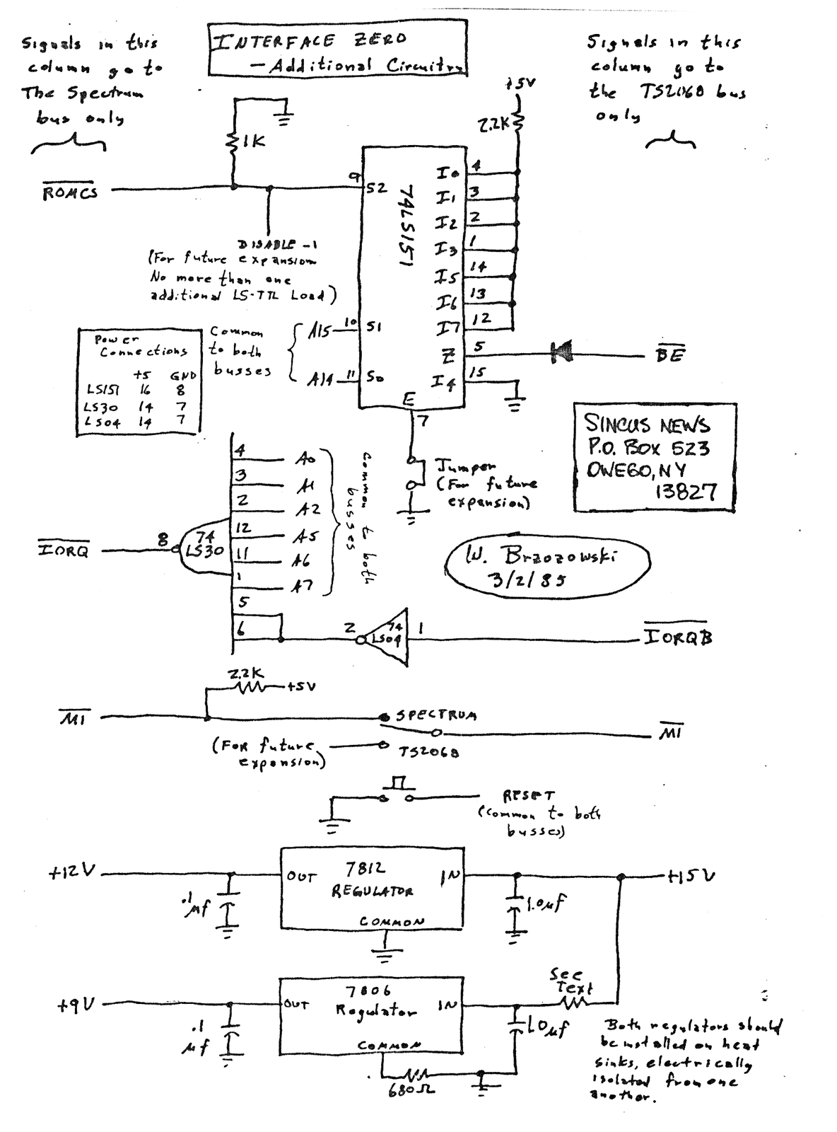
SINCUS NEWS
P.O. BOX 523
OWEGO, NY 13827
SOLUTION TO ROM CONFLICT ON TS2068 COMPUTER USED W/SINCLAIR I/F ONE
WORKS WITH EMULATOR, SPECTRUM ROM, OR ROMSWITCH IN ALL POSSABLE CONFIGURATIONS
THE JOHN OLIGER CO.
11601 WHIDBEY DR.
CUMBERLAND, IN 46229

BE = A15 · A14 · Rom CS (BE, A15 and A14 overbarred)
PARTS LIST:
- 1 PC – 74LS10 IC (APROX. 25¢)
- 1 PC – 680 Ω RESISTOR (5¢)
- 1 PC – IN4148 DIODE (5¢)
LICA
The Long Island Computer Association (all computers) meets the 3rd Friday of each month. Call [phone number omitted] for more info. Or write to LICA Box 71, Hicksville, N.Y. 11802.