
The Sinclair QL was originally constructed with the UK market in mind. Therefore there is some compatibility difficulties with the QL and US monitors. There are three types of color monitors :
1. Composite
2. RGB (TTL)
3. RGB (analog)
Composite monitors will only work properly on US QLs, by connecting their input to the appropriate pin of the 8-way connector.
RGB (analog) monitors are uncommon in the US and are usually quite expensive. Its possible (though difficult) to interface a QL to them, so they are pretty much worth avoiding.
RGB (TTL) monitors are suitable for the QL, but care must be taken in interfacing them. Here is what you need to do :
1. First ensure that the GND, R, G and B lines are wired through.
2. Next hook up the SYNC signals. This may require effort, since the QL only provides two of the possible six signals, and different monitors require different combinations. However, it is always possible to generate the correct SYNCs with a suitable extra gate.
The SYNCs may be as follows :

The QL only provides Vertical Sync +ve and Composite Sync -ve. You can generate the others as follows :
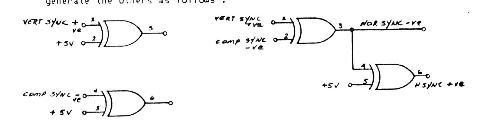
The XOR gates are from a 74LS86 or similar chip. It is sometimes necessary to put a capacitor on a HSYNC line to deglitch it.
3. If the picture is wandering up and down on the screen, try adjusting the vertical hold.
4. The only remaining problem should be overscan : The QL uses around 51.2 microseconds of video compared to the more usual 44. This can often be adjusted inside (or occasionally outside) the monitor : Look for a 40/80 character switch or horiz/vert width controls.
PIN CONFIGURATION FOR QL
Pin   Function   Signal                        Color
---------------------------------------------------------
1     VIDEO      Composite Monochrome Video    Brown
2     GND        Ground                        Green
3     -          Power                         Orange
4     VSYNC      Vertical Sync                 Blue
5     CSYNC      Composite Sync                Yellow
6     RED        Red                           White
7     GREEN      Green                         Red
8     BLUE       Blue                          Purple
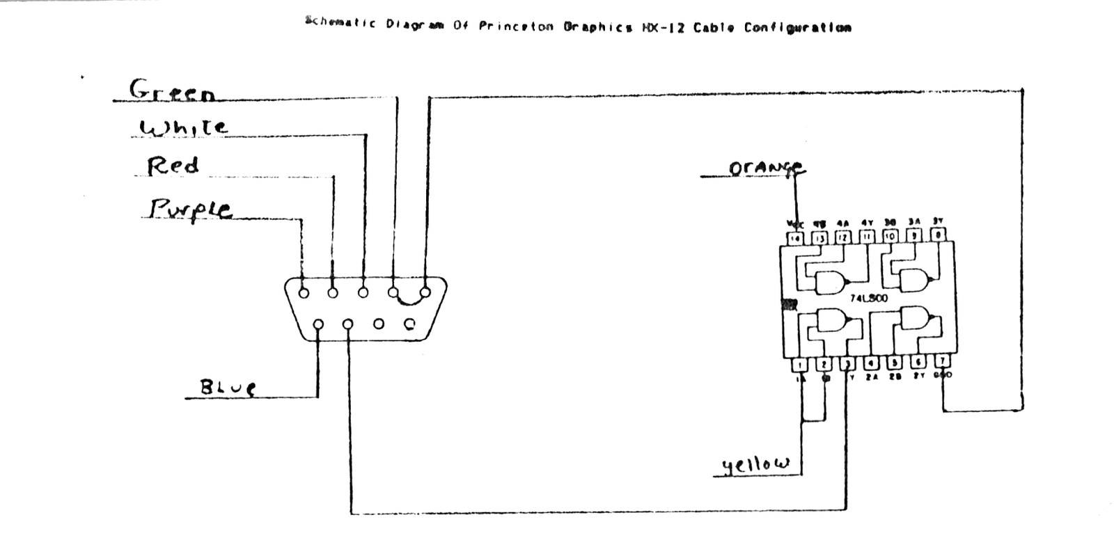
PIN CONFIGURATION FOR PRINCETON GRAPHICS HX-12
Pin   Function    Signal
------------------------------------
1     GND         Ground
2     GND         Ground
3     RED         Red
4     GREEN       Green
5     BLUE        Blue
6     INTENSITY   Intensity
7     -           -
8     HSYNC       Horizontal Sync
9     VSYNC       Vertical Sync
Note : The Princeton Graphics HX-12 Generates :
1. Horizontal Sync +ve
2. Vertical Sync +ve
MONOCHROME MONITORS
Monochrome monitors can be connected by :
1. Soldering the central core of the video input cable to the Brown lead of the 8-way connector.
2. Soldering the outer core of the video input cable to the Green lead of the 8-way Connector.
monitor
A colour monitor can be connected to the QL via the RGB socket on the back of the computer Connection is via an 8-way DIN plug connected to the QL and a suitable plug at the other end
pin   function   signal                           colour
1     VIDEO      composite monochrome video  (3)  brown
2     GND        ground                           green
3     PAL        composite PAL               (4)  orange
4     VSYNC      vertical sync               (1)  blue
5     CSYNC      composite sync              (2)  yellow
6     RED        red                         (1)  white
7     GREEN      green                       (1)  red
8     BLUE       blue                        (1)  purple
(1) 0-5V TTL compatible (active high)
(2) 0-5V TTL compatible (active low)
(3) 1V pk-pk into 75 ohms
(4) May work with the composite video input on some VCRs
A monochrome monitor can be connected using a screened lead with a 3-way or an 8-way DIN plug at the QL end. The connection at the monitor end will vary according to the monitor but is usually a phono plug. The monitor must have a 75 ohm 1V pk-pk composite video non inverting input (which is the industry standard). Both 3-way DIN plugs and phono plugs are commonly available from audio shops.
An RGB (colour) monitor can be connected using a lead with an 8-way DIN plug at the QL end. The connection at the monitor end will vary according to the monitor (there is no industry standard) and will often be supplied with it. A suitable cable with an 8-way DIN plug is available from Sinclair Research Limited.

HINT & TIPS
Tape coming out of the cartridge? Hold it by the top and bottom (the widest part) and lightly tap it on the edge of your desk a few times the tape should slide back in.

General care
- NEVER TOUCH THE TAPE WITH YOUR FINGERS, or insert anything into the cartridge.
- Always store cartridge in its sleeve when not in use.
- Insert or remove cartridge from Microdrive slowly and carefully.
- Ensure cartridge is firmly installed before starting Microdrive.
- Do not repeatedly insert and remove cartridge without running Microdrive.
Tape loops
If a loop of tape appears at either of the two places shown in the diagram above, gently ease it back into the cartridge. Use a clean non-fibrous instrument for this – e.g. the side of a pen or pencil.
NEVER touch the tape with your fingers, for this or any other reason.
Start-up
On receiving your new blank Microdrive Cartridge we advise you to allow it to run for about 30 seconds before writing data on it. Do this by repeatedly using the FORMAT command (see User Manual).
Sinclair Research Ltd, Stanhope Road, Camberley, Surrey, GU15 3PS.