
“Dear Don,
You will also receive a package with a home made LKDOS Dock PC Board for the TS-2068 from me. This letter is being written the day after I sealed up the package. The letter in the package complains about not being able to get my home made I/F PC Board to work. Well, the problems I had with the Dock PC Board made me re-think the I/F troubles. I replaced all the cheap diodes and then replaced two chips that were not exactly the same as on the real LarKen PC Board. Now it works and I can finally send the schematic I started a year ago to Sinc-Link. Below is a copy of the article. This alone was worth the time spent in making the Dock PC Board for you. We both win! Thanks.”
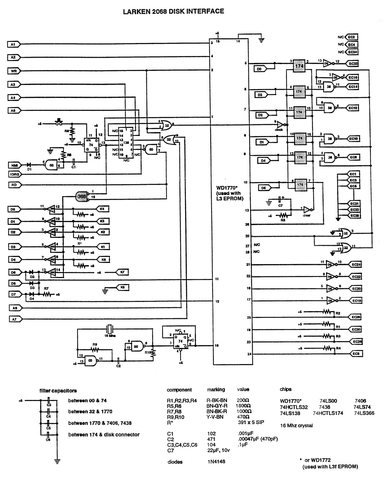
I have been trying for quite a while to verify the schematic that is printed here. I was finally able to verify that my analysis is accurate. It is very difficult to follow all the traces on the chip side of the LarKen PC Board. I broke a socket when trying to peek under the WD1770 chip. After I found out what I had done I became more careful – what would I do if I couldn’t use my drives?
Not shown on the schematic are the +5 connection for the small chips which is on the highest pin number, either 14 or 16. The ground connection is on the opposite corner, 7 or 8.
Please note that data lines D0 thru D5 have two locations so that the schematic would look a little cleaner. The second one is just to the right of the WD1770 outline. Otherwise the Timex edge connections are on the left and the I/F PC Board connections labeled EC1 thru EC34 are on the far right.
Don Lambert probably doesn’t realize what a big help he was by writing to me. In my attempt to prepare my reply to him I learned that the chips used on both the interface PC Board and the Dock PC Board can’t be freely substituted without possible problems. For example I tried to replace the 74LS00 on the I/F with a 74HCTLS00 but it didn’t work! Fancier is not always better. Larry Kenny sure knew what he was doing and he did good. Some chips probably can be substituted but I am not enough of a hardware hacker to know when (or why).
I had also seen in the Chicago Area Timex Sinclair Users Group newsletter that you should always use the 1N4148 diodes that come 10 to the package from Radio Shack (P/N 276-1122) and not the bargain package.
Perhaps the best lesson here is that we as TS users need to communicate with each other. Writing An Article For Our Newsletter is a great way to do this. Don’s letter solved a year’s worth of frustration for me, and he didn’t even know that I had a problem! In order to continue to improve ourselves we must learn from each other. All the big companies are learning that they need to do this. So should we!
LES COTTRELL
[address omitted]
Comments by Don: On the Dock PC Board that Les sent me all chips are socketed and as he mentioned in the letter with the PC Board it keeps the Dock lid from closing all the way. It is held on about a 1/16th of an inch. And when I inserted it into the Dock port I found that it worked as well as the original LarKen Dock PC Board. At a quick glance the main difference of the top of the PC Board is that the LarKen is green in color while Les’s PC Board is brown. Turned over and there are etched leads on the LarKen while Les’s has red wire wrap wire. The placement of parts is very identical.
The main thought that occurred to me is that anyone with the following interfaces: AERCO, Oliger, RAMEX could build a Dock PC Board and secure a copy of the appropriate EPROM and a Format disk could be in business using the LarKen disk interface.
In his first letter, this is what Les referred to :
As you may have suspected from my article in Sink-Link some time ago I had to construct a Dock PC Board in order to verify the schematic that I published. I will use a copy to print this letter on. The enclosed PC Board for you was made from a Radio Shack board and I notice that it holds the Dock door open a little bit. The first one I built was made from a Spectrum cartridge PC Board from Zebra and does not hold the door up. I thought I had an OS-64 PC Board somewhere but I was unable to find it.
I did notice an omission from the schematic, pin 1 of the 74 chip goes to ground. Several components are in little sockets called “Springs”. The transistor, the big diode, the LED and the 470 pF capacitor. I didn’t have the small cap on hand when I started wiring and I really don’t know what the large diode really is. I was lucky on the first one, but using the same one on this PC Board didn’t work. So I tried one marked differently and it did work. Fortunately I had also socketed the big diode on the first one and when I substituted them I was able to locate the faulty part. I enjoy making circuits so this gets chalked up to hobby time.
I assume you have the version L3 and not L3f EPROM. If you are going to use it in a non-LarKen application it shouldn’t matter anyway.
I have not had the same luck with the disk I/F PC Board. I have made two and neither one works. I am an aeronautical not an electrical engineer so I haven’t been able to figure out why the I/F won’t work. I think something is critical around the area of the crystal, but I haven’t figured it out yet. I feel sure I have the schematic figured out but I won’t publish it until I can verify it with a working copy. Do you know of any hardware hackers that I might confer with?
Yes, Nazir Pashtoon is a sure bet. Abed
Sometime back there were QLs selling for $35 as is condition that I missed. I have a collection of Sinclairs and Sinclair stuff in my computer room, I would like to have a sample of a QL even if it didn’t function. Of course I would love to find one that did work. (Check RMG ads and Mechanical Affinity)
(As you can see the last letter preceded the first, I only included it to show how some problems get solved. This time through Bob Swoger who brought up the problem in CATUG meeting, Nazir Pashtoon cautioned about the use of the chips in question.)
Schematics are on the following pages. Send a LSASE to A. Kahale for a complete set which includes the Doc PC Board layouts. (Address is on page 2)