
Let your imagination soar and experience the thrill of flying an airplane — right in the comfort of your own home. The TIMEX Flight Simulator is an educational and fun-filled software cassette that puts you at the controls of a twin-engine, high-performance, propeller-driven airplane. You’ll need skill, steady hands, and a knowledge of aerodynamics and navigation (which you’ll learn from the software) to fly to and land your plane.
Aircraft flight is governed by two aerodynamic principles: lift and forward speed. Lift is created by airflow over the wings of the aircraft, creating lift from below. The extension of the flaps — from the wings — alters the airflow to increase or decrease the amount of lift.
Once off the ground, forward speed keeps the aircraft up, in the air.
LET’S TAKE OFF
Start your engines by entering the command LOAD “FLIGHT” or LOAD “” and press the ENTER key. The program loads in about six-minutes and concludes with a load check. If the check indicates that the load failed, please reload the program.
To begin your flight, select the appropriate option by answering Y (yes) or N (no) to the options displayed on the screen.
- Full Flight
- Landing Practice
- Wind Effects (recommended only for the experienced pilot).
TAKE THE PILOT’S SEAT
Once you have taken your seat in the cockpit, the Instrument Panel, the Navigation Map, the Instrument Landing System (ILS), and the pilot’s controls are used to fly to the airport and land on the runway.
Flying your T/S airplane requires your close attention to the Instrument Panel illustrated and defined below. It will be necessary to pilot the plane along the correct vector (course or compass direction) and the proper heading (compass direction in which the aircraft points) to reach the airport. Then you will have to bank (turn) the airplane onto the final approach and land the plane at the proper speed, rate of descent, and angle of descent.
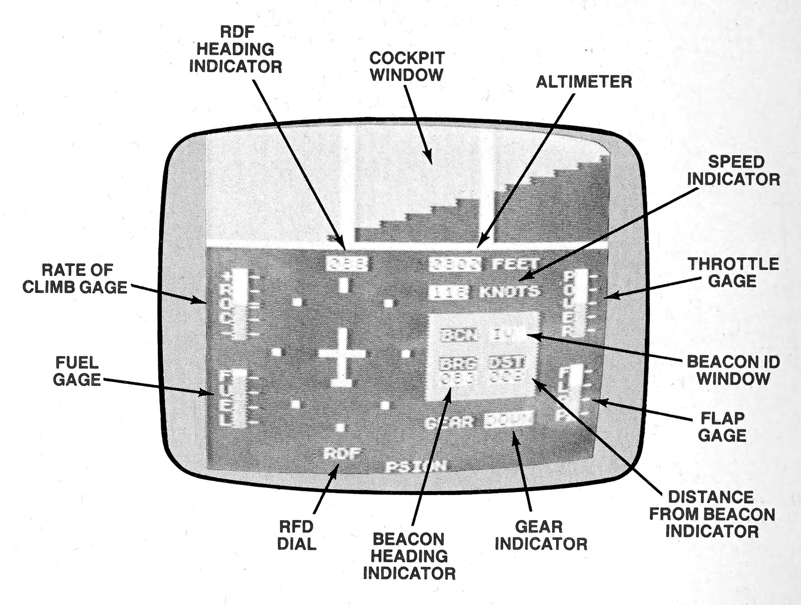
INDICATOR OR GAGE          FUNCTION

ROC (Rate of Climb) Gage   Graduated in units of 600-feet per-minute, it indi-
                           cates the speed at which the airplane is climbing
                           or descending (+ is climbing; - is descending).
Fuel Gage                  Amount of fuel remaining.
RDF (Radio Directional     Facsimile of an airplane, in the center of the dial,
Frequency) Dial            indicates the direction in which the plane is travel-
                           ing. The blinking rectangular light — which ro-
                           tates around the little airplane — indicates the
                           movement of the plane (i.e., banking the plane
                           to turn onto another heading).
BRG Indicator              Bearing (or heading) in which the plane must
                           travel in order to reach the Beacon onto which
                           the RDF has been "locked."
GEAR Indicator             Reads UP or DOWN depending upon whether
                           the wheels have been raised or lowered.
DST Indicator              Distance — in nautical miles — from the Beacon
                           onto which the RDF has been "locked."
FLAP Gage                  Marked in increments of 1/4, to indicate how much
                           flap has been applied.
Beacon ID Indicator        Identifies Beacon (there are a total of seven) to
                           which the RDF has been "locked."
Throttle Gage              Divided into units of 20%, to indicate the amount
                           of power supplied to the engines.
Speed Indicator            Speed — in knots — of the aircraft.
Cockpit Window             Light area is sky; dark area is ground. View
                           changes when aircraft climbs, descends, or turns.
Altimeter                  Height — in feet — of airplane above sea level.
RDF Heading Indicator      Numerical compass-point value of heading
                           (direction) in which the plane is traveling.
THE PILOT IS IN CONTROL
Several controls are needed to fly your plane. The principle ones — on an actual airplane — are the control stick, flap, throttle, and landing gear.
For example, moving the control stick sideways works the ailerons on the wings so the airplane banks to the left or right, as appropriate. In a similar manner, pushing the control stick forwards, or pulling it backwards manipulates the elevators on the rear of the plane to cause the plane to climb or descend, respectively.
Your T/S aircraft is equipped with the following controls, which simulate those of a typical aircraft of this type.
KEY          FUNCTION
Up arrow     When pressed, plane loses altitude.
Down arrow   When pressed, plane gains altitude.
Right arrow  When pressed, plane banks (turns) to the right.
Left arrow   When pressed, plane banks (turns) to the left.
P            When pressed, plane gains airspeed.
O            When pressed, plane loses airspeed.
F            When pressed, the flap is lowered.
D            When pressed, the flap is retracted.
G            When pressed, the landing gear is either lowered or raised.
B            When pressed, successively displays the ID of each Beacon.
M            When pressed (when the Instrument Panel is displayed), the
             current display is erased and the Navigation Map appears;
             when pressed with the Navigation Map displayed, the
             Instrument Panel reappears.
V            When pressed (when the Instrument Panel is displayed), the
             current display is erased and the ILS appears; when pressed
             with the ILS displayed, the Instrument Panel reappears.
MAPPING OUT YOUR FLIGHT
It is a good idea to use the Navigation Map to travel to the airport. To view the map (when the Instrument Panel is displayed), press the M key on the keyboard.
The Navigation Map is illustrated below. On the map you’ll find the four points of the compass, the Beacons, the current heading of the aircraft, and an aircraft hazard consisting of a series of hills to the East of the runway. These hills rise to an altitude of some 1500-feet above sea level and are located about 7½-miles from the runway. The position of your plane is shown as a moving, blinking, rectangular light. As you can see, the runway runs on an East-to-West axis; therefore, it will be necessary to bank onto a heading of either 90- or 120-degrees to start your final approach.
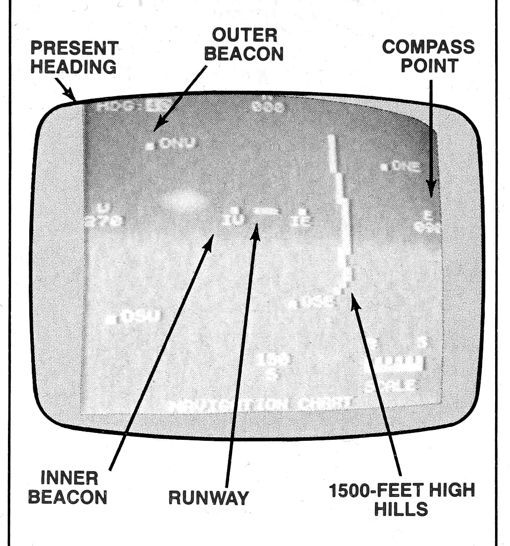
In order to approach the runway properly, the airplane must gradually descend at an angle of about 3-degrees. This angle of descent implies a height of about 6,000-feet at 20-miles from the runway, 3,000-feet at 10-miles out, and 1,000-feet at the 3½-mile mark. You can easily make the height adjustments “on the fly.”
At the start of your flight, the computer will randomly select a starting point. From this position, you must find your way to the runway.
To chart your course, select an Outer Beacon as a guidepost and press the B key (the Instrument Panel is displayed during this step) until the Beacon ID is displayed (a Beacon is a radio beam which plots the position of the aircraft based on the intensity of the signal). Note the heading in the BRG “window” and bank the aircraft until that heading is displayed in the RDF Heading “window” above the RDF Dial.
As the aircraft approaches the 90 E / 270 W axis, you will probably need to bank the airplane to line-up with the runway. Do so by selecting the appropriate Inner Beacon (the Inner Beacon is about 2-miles from the runway) and adjust your heading accordingly.
Finally, as the Inner Beacon is approached, the heading of the aircraft may need to be slightly adjusted to obtain a more precise alignment with the runway. The Runway Beacon (there is no ID designation for this Beacon in the Beacon ID “window”) can be utilized to obtain the heading to turn the plane onto its final approach.
TOUCHDOWN
In a manner analogous to the standard-shift automobile, on which the clutch, shift lever, brake pedal, and steering wheel must all be engaged when stopping the vehicle, full flaps must be applied, the landing gear must be lowered, airspeed and altitude must be reduced, and the plane must be aligned with the runway prior to the landing.
When you turn onto the final approach, you’ll want to use the Instrument Landing System (ILS) (illustrated below) to achieve a successful touchdown.
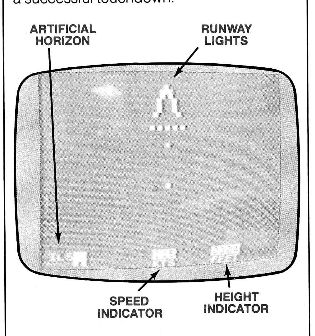
At the top of the ILS you’ll see the horizon (light shaded area). Below it is the runway and its landing lights. As your airplane approaches touchdown, the display moves towards you — just as if you were actually piloting a real plane.
On the bottom of the ILS you’ll find the artificial horizon, a speed gage, and a height (Radio Altimeter) indicator.
The square gage on the far left-side of the ILS acts as an artificial horizon; it indicates the start of the runway relative to the position of the plane: The start of the runway is displayed as a flashing light within the gage. If the plane is squarely aligned with the runway, the light will flash in the center of the gage; if the flashing light is at the left- or right-side(s) of the gage, the position of the plane is slightly off-course and should be adjusted before touchdown. When the flashing light is above the gage, the plane is descending too steeply; if below the gage, the plane is not descending steeply enough.
Aircraft speed is displayed in the center indicator. Reduce airspeed as you land, but do so carefully so the engines won’t stall.
Finally, the radio altimeter uses a radio-beam reflection system to measure the height of the airplane’s wheels above the runway. This height (in feet) is displayed in the far right indicator on the ILS.
PILOT TALK
Although we don’t want to eliminate the challenge and fun you’ll experience while learning to fly with the TIMEX Flight Simulator software cassette, the following tips will help you make a smooth and successful flight:
- Pay careful attention to the indicators and gages on the Instrument Panel.
- Utilize the Beacons as a navigation aid to reach the airport.
- Don’t let the airspeed drop to the point where the engine stalls (there is a minimum speed, but we won’t ruin your fun by telling you what it is).
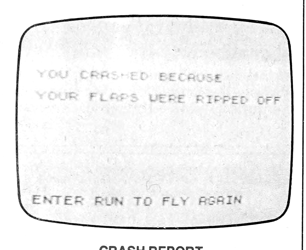
- Avoid engaging full flaps and landing gear at excessive rates of speed; if you do, they will be torn off the aircraft and you will crash.
HAPPY LANDINGS!