
I. Bill Lawson article (Nov/Dec 92 Toronto’s SINC-LINK) mentioned a myriad of symptoms of his malfunctioning QL system. I hope he has resolved and sorted out these problems. The symptoms he mentioned;
Cursor disappears and machine locks up.
READ/WRITE FAILED
Double listing of Directories.
Use DELETE, get PROGRAM DOES NOT EXSITS.
Windows changing constantly.
Code? scrolls by.
MINERVA ROM is on board,
and a few more, apply to approximately a dozen QLs in my user group (CATUG) and my own. These problems invariably surface when a daughter-board with Minerva or QDOS EPROM is installed in the QL. To solve these problems, proceed as follows:
a) All the important integrated circuits in the QL are socketed. Socketed computers from LISA to the first shipments of ATARI ST and other computers were plagued by unreliable operation. The same is true of the QL. Many times the microdrive problem and unreliable video blanking is directly traceable to the ZX8302 and ZX8301 chips. Note that these two ICs are CMOS, and static-sensitive, touch a grounded metal object with your fingers before you touch the ICs. When you open your QL, it is advisable to spray the pins and sockets of these ICs, as well as the pin rows and sockets of other ICs with a “tuner cleaner”, such as Radio Shack #64-3320, or equivalent. After spraying, use a flat-bit screw driver, or a butter knife to displace the chip slightly upwards from both ends. Spray again, and press the integrated circuits back in place. This cleaning should suffice for at least a year.
b) As mentioned earlier, many users who had fully functional machines, started having problems when they installed a small EPROM daughter-board inside the QL. After carefully studying the problem in about a dozen cases, I concluded that the problem is caused by hairline cracks in the copper traces of the daughter board. How are these hairline cracks caused?
After watching our members, and my own practice of how I would install the daughter-board on the QL motherboard, it became obvious that we ourselves were the culprits. To explain, normally we would first install the daughter-board by pressing on the corners of the board, and then press-in the EPROM. Both the procedure as well as the order in which the task is performed are wrong. Why?
The daughter-boards we were using, are flimsily constructed from very thin copper traces (to keep costs down, this is true of all peripheral boards, and the QL motherboard). As the figure shows, two sockets are installed side-by-side, with approximately 0.2″ spacing, one socket that is used for the EPROM is an ordinary dual-leaf socket, and the other one is a machined socket. The pins of the machined socket protrude, and is fitted in the ROM socket on the QL motherboard. In order to install two sockets side-by-side one has to saw-off the socket stabilizing bridges (two or three). The consequence of this is that when you want to install an EPROM in the normal socket, it flexes the socket rows sideways so much that some times it is not possible to install the EPROM. This flexing causes the hairline cracks in the copper traces on the back of the daughter-board. Belatedly, one discovers that in order to install the EPROM, one has to hold the two rows of the socket pins of the normal socket vertically by one hand, and then fit the EPROM in the socket. We discover this after we have already caused damage to probably more than one trace.
The second mechanism causing the cracks, is the way we normally install the flimsily made daughter-board, by pushing on the corners of the board. This method of installation causes too much pressure on the corner pins of the machined socket, and possible hairline cracks. As such, the suggested procedure for installation is to :
- First install the EPROM on the daughter-board, while holding the normal socket in a vertical position with one hand, thus avoiding the flexing of the pins of the normal socket.
- Second, install the daughter-board on the motherboard by pressing on TOP of the EPROM, thus causing the pressure to be equally distributed on all the pins of the machined socket.
All these hassles could have been avoided if the boards were properly manufactured. For example, metalization both on top and bottom of the daughter-board would have helped. Most importantly, instead of using a low cost machined socket, the use of DIP socket carrier (say Digi-Key #ED6028, $3.26 ) would have totally solved the problem. In this case you will have the benefit of machined pins, with pins flush on top, thus allowing the normal socket to straddle the socket carrier pins on top, without having to saw off the stabilizing plastic bridges.
The hairline cracks that I mentioned are hard to see even under a magnifying glass. Static testing by continuity measurements (using a VOM) could also be misleading. One can dynamically test by say, using a logic probe. One may even be tempted to cure the problem by putting solder globs on the affected traces. I recommend against it. The only sure method of solving the problem is, to do point-by-point wiring between the pins of the two sockets. This is much easier than it sounds. As shown in the figure, the two sockets are separated by a distance of 0.2″, with all the respective pins connected by copper traces, except pins 1, 20, and 22. I use bare wrapping (28 gauge) wire. Make a tiny hook on one end of the wire, solder it to the pin, wrap the wire on the corresponding pin of the other socket for half a loop, solder and cut the wire with a razor blade or X-ACTO knife at the base of the pin. Do all the 25 pins shown in the diagram. This will, with high probability, solve your problem. In the worst case you may have to duplicate all the traces on the back of the daughter-board using wire-wrap wire. Do not use a soldering iron rated higher than 15 watts.
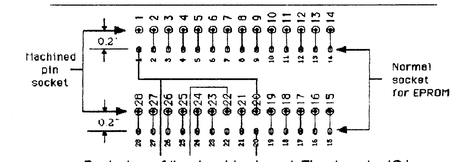
c) A third source of the cracks, is the protrusion of the daughter-board on top of the QL mother-board, and the pressure applied by the back of the keyboard. On the Samsung QLs, there is a screw on the back of the keyboard, which interferes with the top of the new EPROM that you install. One must remove this screw. Even the removal of this screw does not solve the problem, always. It is suggested that of the eight screws holding the keyboard and the base of the QL together, two screws, one in back and one in front, not to be installed. These are the screws which are left of center, roughly in alignment with the ROM sockets. It is worth mentioning, that depending on the height of the daughter-board, even the mother-board can be flexed by the pressure exerted through the daughter-board from the keyboard.
II. In the Mar/Apr 93 issue of Sink-Link, an article “Notes On QL Lock-Ups” by Hugh Howie, and I quote; “I know of one person who has four QLs and is only now starting to have some success with one of them. Power Surges?” Some QLs have exhibited this problem since its introduction into the market place. I have analyzed the problem, and I believe I have a low cost solution. I suggest that people facing this so called HEATING problem, send me $2.00 cash, for the cost of a device, jiffy-bag, and mailing by return mail.
PS. After the above article was published, I received the Mark I version of Minerva 1.97. The daughter-board carrying a 1990 Copyright, is the best I have ever seen (in the QL market). It addresses all my objections. It has metalization on top and bottom with machine inserted metal eyelets connecting the top and bottom traces, with ground planes. Best yet, they have used only one machined socket for both the EPROM and the connection to the mother-board.
Nazir Pashtoon
[address omitted]
The heating and cooling of the Printed Circuit Board (the turn ON and turn OFF of the computer) causes expansion and contraction of the copper foils (traces) that can cause intermittent loss of circuit continuity due to tarnish at the ‘hairline cracks’. Abed