
RGB vs Other Methods
Ever since I purchased my TS2068 I have longed for a REAL RGB interface. Sure, the display is OK on my 19″ Sony, but the color is “washed out” and there is that ever-present background hash. I thought that by attaching a composite monitor to the monitor jack would at least clean up the hash….but no, the hash remains! Thus began my work on THIS article.
Composite video is simply a combination or mixture of the three basic signals common to all CRT (Cathode Ray Tube) based display devices. First, there is the VERTICAL SYNC which is used to ‘lock’ the picture vertically. Second, there is the HORIZONTAL SYNC which ‘locks’ the picture horizontally. Then there is, of course, the VIDEO INFORMATION which supplies the actual picture.
COMMON TVs
In the case of color displays there are three methods of getting these signals to the monitor or TV. In the begining…….there was the RF modulator. This is simply a VERY low power broadcasting station! All three basic signals are combined to from the COMPOSITE signal, and then ‘broadcasted’ via a cable to your favorite TV. You, in turn, select channel 3 or 4 and, voila! The ‘Gulpman’ appears on your screen. The advantages to this type of interface are ease of hook-up, cost, and availablity of the common color TV. The disadvantages are the BANDWIDTH of this type of interface are LOW. This is seen as poor picture quality and ‘washed out’ color. There are two reasons for this; 1) The tuner circuitry in the TV and RF modulator in the TS2068 cannot handle the high resolution modes that our computer is capable of. 2) The ‘common’ TVs’ CRT DOT-PITCH is not good enough for high-resolution color images. (More on this later). Then there is that ANNOYING ‘background hash’!
COMPOSITE MONITOR
The second method is to send the composite signal directly to the TVs’ CRT circuitry, bypassing the tuner and the computers’ RF modulator. This method works quite well because we are bypassing all that circuitry. The display looks MUCH better but the color is still ‘washed-out’ due to the fact that the DOT-PITCH of the TV is large. Also, the circuitry needed to combine the color/sync signals in the computer end, and the circuitry needed to separate the color/sync signals in the monitor end, add to the distortion of the display and color. I probably would not have noticed this except that I also have a QL with its’ RGB monitor and there is just no comparing the RGB with a standard monitor or TV. So the Monitor connection is much better than the RF modulator but, still, is not the best interface available.
RGB MONITOR
The third method is, by far, the most impressive in that the quality and control of the color signals are absolute. This is accomplished by sending the three color signals SEPARATELY to the monitor along with a COMPOSITE SYNC signal containing the VERT and HORZ syncs. The disadvantages to this method are the multi-wire cable needed to connect the monitor and the cost of the monitor. Why is the RGB monitor more expensive? Most of the cost of an RGB monitor is tied up in the CRT RESOLUTION and circuitry to support it. A typical TV has a DOT-PITCH ( DOT-PITCH is the distance between adjacent CRT pixels ) of about .85mm, where a good RGB monitor such as the QL Vision monitor has a dot-pitch of .38mm. You can really see the difference!
So we have two goals here; one, to convert our machines to RGB and two, to get rid of that ANNOYING ‘background hash’!
CONSTRUCTION
This circuit was derived from a circuit appearing in the 2068 Technical Manual, page 57 and was modified to work with the QL Vision monitor, although with the proper connector, it should work for any RGB monitor. If you don’t have this book, GET IT! This is the single most useful book for the 2068 and is published by TIME DESIGNS MAGAZINE.
We need a VERY CLEAN supply for this circuit to eliminate the background hash. This hash is generated by the computers’ SWITCHING REGULATOR. To accomplish this we will be ‘double regulating’ the supply to the RGB sync circuit. This circuit just extracts the SYNC signals from the TS2068 COMPSITE out-put. The color signals already exsist in the TS2068!
+12 VOLT REGULATOR
Using proper static precautions, remove the top keyboard case and then the internal PCB. Using figure #1, locate and remove the 78L12A regulator. It looks like a garden-variety transistor. Use a solderwick or solder-sucker to remove the solder from the regulators PCB holes and then gently remove the wire leads. Next, install a 78M12 or 7812 regulator in its’ place using figure #2 as a guide to orienting the new regulator. NOTE that I’m showing the BACK-SIDE of this regulator UP. Now cut a 12″ piece of insulated wire and solder on end to the regulator as shown in figure #2. Leave the other end free for now. Leaving the PCB out of the case and making sure the PCB is insulated from contacting any metal, connect your TV and power up the computer. You should get a NORMAL display with the Sinclair copywrite notice. If you don’t POWER OFF!!!! Then check the orientation of the new regulator again and correct. If you have a voltmeter you can also check the output of this regulator to insure that it is at +12 volts. This point is the same point as the wire that was attached to the regulator in figure #2.
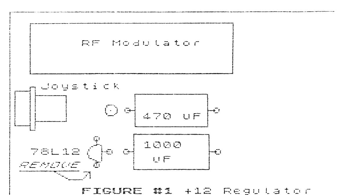
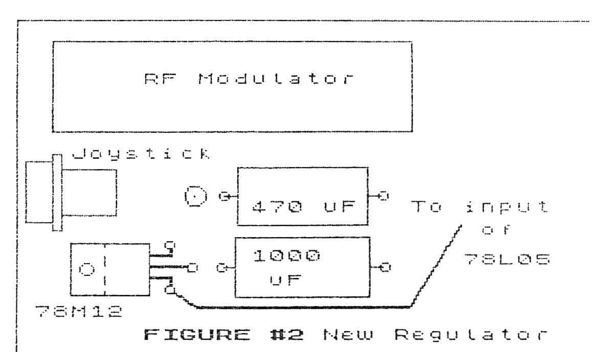
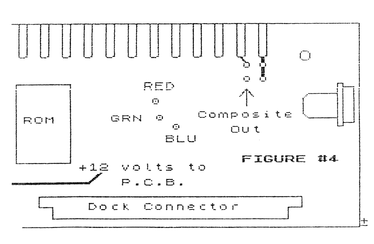
Using the schematic in figure #3 assemble the circuit on a small piece of perf board. Then pick an area inside the case to mount the small perf board assembly, (I used the area just above the right hand joystick connector.) Use a small piece of two-sided foam tape to mount the perf board. Next, attach the +12 volt wire previously soldered to the new +12 volt regulator and solder it to the proper point on the perf board (The input of the 78L05 voltage regulator). Now run a small wire from the computer’s composite out shown in figure #4 to capacitor C1 on the perf board (see schematic in figure #3). Now run a ground wire from the perf board (emitter of Q2) to a ground point on the computer PCB. A good place is the ground plane just above the right joystick connector. Take the 6-wire shielded cable and solder the wire you’ll be using for the COMPOSITE SYNC to the perf board (collector of Q2). Solder the wires you’ll be using for the Red, Green, Blue signals to the computer’s PCB at the points shown in figure #4, then solder the wire to be used for monitor ground AND the SHIELD wire to the main ground point in the computer which is located in the center of the computer PCB. It has a large wire soldered there with many other smaller wires and a cap attached to it. Lastly attach an 8 pin DIN socket to the other end of the 6-wire cable, or if you’ll be using a different monitor, the proper plug to match that monitor.
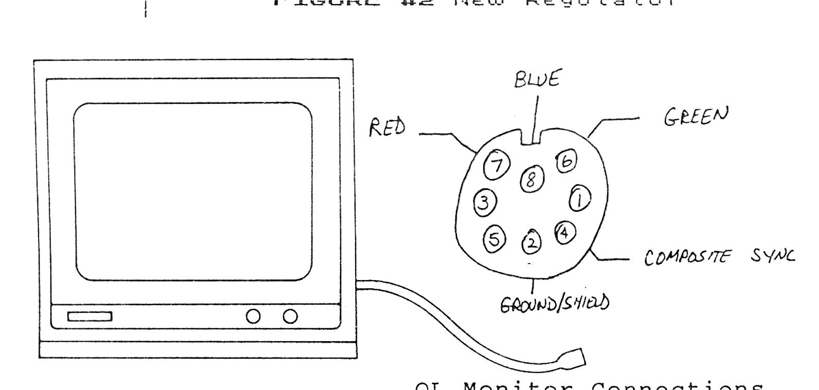
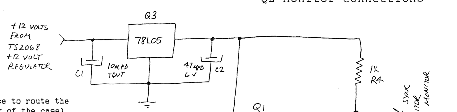
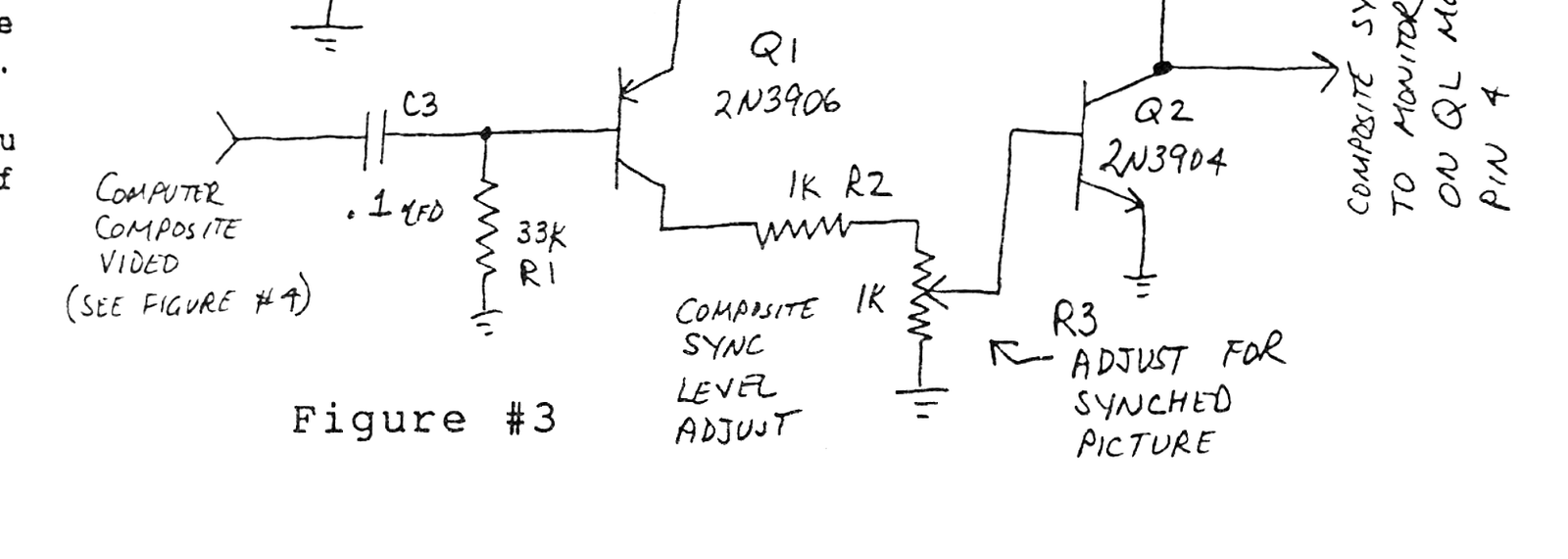
Reassemble the computer into the case and pick a place to route the wire out of the back of the computer (I chose the center-back of the case). Connect a TV and power supply to the TS2068 and power up. You should get the copyright notice as normal. Power off and connect the RGB monitor ( you can leave the TV connected) and power up again. You should get some sort of display on the RGB. Adjust the potentiometer R3 to get a stable display…NOTE NO BACKGROUND HASH!!!This circuit is designed for low-going composite sync monitors which comprises about 90% of the RGB monitors available. If yours is one of the 10%, drop me a line and I’ll help you out! All parts are obtainable at Radio Shack, including the 8 pin DIN socket. One source is a Tandy 1000 keyboard extension cable which has both a male and female in-cable connectors plus a 6-wire shielded cable for $14.95 as part number 26-1389. If you want only the female connector they only stock the PCB mountable connector and you’ll have to ORDER that as part number AJ7550 for $1.00 (It’s a replacement socket for their Tandy 1000 computer!).
LETTERS, NEW BBS, OFFERS!
Thanks for the many letters you have sent in support of my articles! I have improved the TS2016 ram pack upgrade to allow usage with the TS1500. Thanks to reader Earl Dunnington of Boynton Beach, Florida, for inspiring me to accomodate the TS1500. For those of you wishing the latest improvements in the upgrades for the ram pack or any other of my articles, just send me a SASE and I’ll return the latest info. Also Mark Fendrick, columnist for Computer Shopper, has started up a new Sinclair BBS called “SINCLAIR at NIGHT”. He has generously named me as the ZX81/TS1000 conference leader, so you can find me daily on that BBS. Please call in on this board and support these great little machines! Hours are 2300 to 0600 daily, phone 718-627-1293. There curently are also TS2068 and QL sub-boards (conferences) with new conferences added to the arrival of new computers such as the THOR. You’ll also find any late-breaking info about my articles on that BBS in the ZX81/TS1000 conference. For those of you who are not hardware oriented, I am extending an offer I started with the Vancouver Sinclair User Group to upgrade either the TS2016 ram pack for $25 US, or the TS1000 internal 64K upgrade for $40 US. Just mail the ram pack or computer or both (as many did in VSUG) and I’ll convert and return via insured mail. It would be a good idea to check with me ahead of time to see how “swamped” I am. You can do this by mail (85-48 66th Road, Rego Park, NY, 11374), Compuserve ([e-mail address omitted]), or on the “Sinclair at Night” BBS.