
The Project
A little over a year ago I decided to start building a robot. I had no idea that it would lead to a project fully controlled by a computer. However, as I started reading more about robots and the robotics law, I realized that a true robot had to be a self-contained entity able to operate as independently as possible. At that time I did not even know what a ZX81 was, but, after a few months into the robot project, I bought my first ZX81 computer (the family now owns two). Even then I did not immediately realize the possibilities of ZX81 control. About three months later after reading about the expansion possibilities of the ZX81, I decided to try to combine the ZX81 with the robot.
If you are not interested in such a large computer control project, the hardware, software, and interface methods described here can easily be applied to a smaller project such as a robot arm.
The Robot
I will not describe the actual construction of the robot in any detail. The design for the robot was based on the Radio-Electronics magazine reprint series of articles titled, “Build this robot for under $400.”
Although my project robot has many similarities to the RE Unicorn-1 robot, it also has many differences. As complete as the series of articles was, there were many errors and incomplete explanations of the design.
The basic improvements on the physical design are as follows. The diameter of the body was reduced to sixteen inches. It was obvious that a body any wider, with arms added, would have trouble navigating through household doorways and other tight spots. The drive wheels were placed in the front to pull the robot around and aid in traction. This moved the battery to the rear and aided stability. The base was made the same diameter as the body for aesthetic reasons. Although small access doors were located in both the front and back of the base, the required access to the base was achieved by making the entire base plate of the upper body, with turntable, hinge backward to allow full access to the inside of the base. And finally, the computer with expansion board was located on the top and underside of the hinged lid.
To save money and learn as much about the input/output circuitry as possible I purchased the Computer Continuum expansion board and the Zodex RX-81 input/output boards in the bare board form and built them up from components purchased separately. I built up all the other boards and even etched some myself.
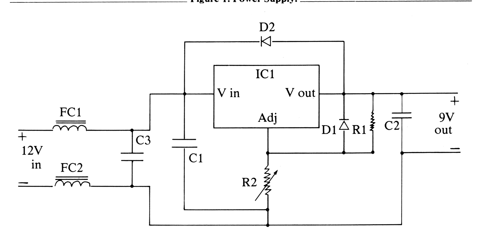
IC1        LM350, 3 Amp adjustable power regulator
D1,D2      1N4002
R1         120 Ohm, 1/4 watt
R2         5K Ohm adjustable pot (10 turn)
C1         .1 MFD, 25V
C2         1 MFD, 15 V
C3         2300 MFD, 33VDC, 50V surge
FC1,FC2    125 uH, 3.5 Amp hash filter choke

Note: Heat sink IC1 well (3 to 4 Sq inches)


The Power Supply
The biggest problem on the electronic side resulted from choosing to run everything from a single 12 volt battery. The DC motors and the controlling relays caused problems because the voltage and amperage (frequency) spikes which they generate wreak havoc on the computer. The single battery, originally a large motorcycle battery since replaced with a small car battery, simplified the power management problem.
The final solution to the spike problem had an added benefit for the ZX81 used as the home computer. If you have never tried to use a small computer in Europe, with the “spikey mains” as the British refer to their noisy wall power, you cannot dream of how many ways a computer can bomb. The problem is the same here in West Germany where I am currently living.
The power supply (Figure 1) solved all spike problems. For the robot, the 12 volts in comes from the battery. For a home computer application, the 12 volts in would come from a rectified 12 volt transformer output.
The key to the success of the design is the large can-type capacitor (C3) and the hash chokes. The capacitor is available from Jameco, and the hash chokes were ordered from Mouser. The power supply works so well on my wall-powered ZX81 that all problems previously attributed to LOADing and SAVEing glitches have all disappeared. Also, with the large can capacitor, the house lights can momentarily dim with no effect on the computer.
The Control Relays
The heart of the robot control is the 5 volt double pole double throw relays driven by the computer output which in turn activate the 12 volt robot motors and solenoids. The functions of these relays are listed in Figure 2. Although only sixteen are used, the 44 finger circuit boards used are capable of handling up to twenty relays. In my design these relays are double buffered from the computer output drive with both transistor switches and small DIP relays. The 12 volt relays (5 volt coils) are wired similar to the RE reprint layout with some important differences which will be explained later. Figure 3 gives a complete wiring table from the RX-81 output through the 12 volt connections to each motor/solenoid.
[Figure: Figure 2. Relay Functions.]
RLY   Function (Motor Drive)
 1    Upper body rotate left
 2    Upper body rotate right
 3    Left drive wheel forward
 4    Left drive wheel reverse
 5    Right drive wheel forward
 6    Right drive wheel reverse
 7    (not used)
 8    (not used)
 9    Left shoulder down
10    Left shoulder up
11    Right shoulder down
12    Right shoulder up
13    (not used)
14    (not used)
15    Left elbow down
16    Left elbow up
17    Right elbow up
18    Right elbow down
19    Right hand close
20    Right hand open
[Figure: Figure 3. RX-81 Output.]
                RX-81 Output              Trans switch    DIP relays       5v relays
RLY  DO-7       wire color    PC conn    Base   Coll     Coil  Contact   Coil  Contact
                                         (in)   (out)    (in)  (out)     (in)  (out)
 1   1-5        blu/sht         10        L      10       L     10        20    W
 2   1-6        wht/blu         11        M      11       M     11        17    V
 3   1-1        wht/grn          6        F       6       F      6         R    11
 4   1-2        grn/wht          7        H       7       H      7         L    12
 5   1-3        wht/gry          8        J       8       J      8         6    D
 6   1-4        gry/wht          4        D       4       D      5         3    C
 7                              20        X      20       X     20        21
 8                              21        Y      21       Y     21        15
 9   2-1        wht/grn         12        N      12       N     12         N    S
10   2-2        grn/wht         13        P      13       P     13         K    13
11   2-3        wht/gry         14        R      14       R     14         7    E
12   2-4        gry/wht         15        S      15       S     15         2    F
13                              22        Z      22       Z     22        19
14                               5        E       5       E      4         P
15   2-5        blu/wht         16        T      16       T     16         M    U
16   2-6        wht/blu         17        U      17       U     17         8    T
17   2-7        org/wht         18        V      18       V     18         5    J
18   2-8        wht/org         19        W      19       W     19         1    H
19   1-7        org/wht          9        K       9       K      9        18    22
20   1-8        wht/org          3        C       3       C      1         4    10
     Gnd        blu              2          2,B               2               A
                                        (emitters)
+5 volts                                                        3

RX-81 output board #1 wired as "out 7".     RX-81 output board #2 wired as "out 6".

Example: Output DO from board wired  as "out 7" is listed above as 1-1.
I will now quickly walk you through Figure 3 describing the control of relay #1 and then explain each component in more detail.
Relay #1 is controlled by the output of D4 from one of the RX-81 input/output boards. D4 is designated as 1-5 meaning that it is the fifth of eight parallel outputs on the first RX-81 output board. It is connected by a blue with white stripe wire to finger 10 of a short PC board which is plugged into the circuit loads, depending on the size of the DC motor or solenoid driven.

R1 220 Ohm 1/4 watt
Large DIP mounted relays of sufficient amperage can be used but they can be expensive ($4-5 each). I found some miniature 6 volt DPDT relays rated at 3 amps which were cheaper and worked quite well. One source is the All Electronics Corp. at only $1.75 each. Sixteen to twenty of these can be packed on a 4 x 5 inch PC board, although the more expensive high amp rated contact DIP relays would not have to be packed so closely.

D2 1N4148
C1 .01 MFD, 10V

**For DIP #1 this would be wired to connector L.
**For DIP #1 this would be wired to connector 10.
An example of both the forward and reverse relays is shown in Figure 6. They are wired together to prevent accidental shorting of the output to the motor. Each of the two relays for each motor (one for forward and one for reverse) provides opposite polarity power. If you made no special wiring provision, it would be possible to activate both relays at the same time and cause a direct short circuit between +12 volts and ground. Two extra wires between the two relays, along with a modification of a direct hookup, protect against this.
If you look at Figure 6, you will see that the coil input (+5 volts) to the righthand relay coil (relay #1) will not cause the coil to be activated unless relay #2 (lefthand relay) is not activated. This is because the coil of relay #1 has no ground to complete the circuit unless relay #2 is in the normally closed position. Notice that the ground for relay #1 coil is supplied through the normally closed contact of relay #2. This way, even if both the reverse and forward circuits are activated at the same time, only one will work.
Also note the diode and capacitor protection on these relays. This feature is especially important as the unloading of these relays introduces a lot of unwanted into the electrical circuits.
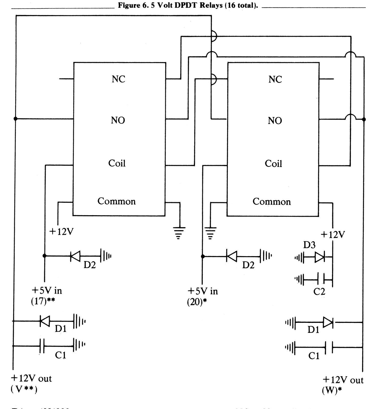
D1    1N4002
D2    1N4148
D3    1N5401
C1    .01 MFD 25V
C2    22 MFD 35V

NC = Normally closed contact.
NO = Normally open contact.

*Wired to this connector if relay #1.
**Wired to this connector if relay #2.
For some motors in your robot the 12 volt output of the relays in Figure 6 will be hooked directly to the motor leads. However, you may wish to install limit switches on the mechanism of some motor drives such as the arm elbow motor. The limit switches are normally closed contact microswitches. A simple but effective limit switch circuit using two diodes and a four terminal, terminal strip is depicted in Figure 7. If you happen to get it wired backwards (50/50 chance), just reverse either the 12 volt input leads or reverse the motor output leads.

Input Stimuli
Before we turn to software, a few words about input stimuli to the input board. First, the input board is the same board that is used for output, the Zodex RX-81 in this case. The RX-81 provides eight input lines and a ground. To input a signal to D0, or as I refer to it, 1-1 (input line #1 of RX-81 board #1), you just connect the input line to ground.
For my robot I installed normally open connect microswitches to the exterior of the robot with spring wire extensions covered with foam rubber pads. The bumper switches include one as a front bumper, one as a right bumper, and one as a left bumper. I actually installed two sets of two front bumper switches each, one set with a spring wire horizontally between them and another set with a spring wire vertically between them. This arrangement gives a larger striking area if the robot runs head on into something. The obvious expansion of the input switch system would be the addition of other types of sensors such as an ultrasonic range measuring system, like the one from a Polaroid camera focusing system, available for about $130.
An alternate way to accept input commands to the computer is to wire the external microswitches sensors as keys on the ZX81 keyboard. This method works, but it is not totally satisfactory. The computer can be set up to scan the keyboard for specific key inputs, but the problem arises when two keys (or micro switches) are closed at the same time. This can easily happen if the robot works its way into a corner and hits the front and side sensors together. The computer will not normally accept any keyboard input if this happens and it could even be seen as an illogical input and blow the program.
With sensors wired to the RX-81 paralled input board a program can be written to accept any combination of simultaneous sensor inputs at the same time, and recognize them. More on that in the software explanations.
Writing the Software
When your robot motors and bumper switches are wired up to the ZX81 computer as described, you are ready to start writing software to “control the world” or at least the world of your robot. All programs are for 8K ROM. The second listing will require 16K RAM.
The data sheet that comes with the RX-81 explains a few programming instructions to get you started, but my programs written for direct robot control will be explained in detail. All programs start with the line of machine language in the REM statement (do not forget to delete the first REM statement containing the program name before running the program) followed by POKE 16517, 79.
To activate an output line you first POKE the binary number for the line, then POKE the number of the output board (if you have more than one board) and the activate the command with an OUT USR statement. For example, if you wanted to activate output line #3 on an output board wired as “OUT 7” you would write the program as follows:
100 POKE 16522,4
(addresses line #3)
110 POKE 16524,7
(addresses board wired as OUT 7)
120 LET OUT=USR 16521
(activates command)
As listed in Figure 8, this would make the right wheel move the robot forward. To make the right and left wheels go forward use the following lines:
130 POKE 16522,5
(addresses line #1 and #3 together by adding their binary numbers 1 + 4)
140 POKE 16524,7
(addresses board wired as OUT 7)
150 LET OUT=USR 16521
(activates command)
To turn these motors off, POKE 0, as follows:
160 POKE 16522,0
(deactivates all output lines)
170 POKE 16524,7
(addresses board wired as OUT 7)
180 LET OUT=USR 16521
(activates command)
[Figure: Figure 8. Software Commands.]
Function          Relay   Output   POKE A,   POKE B,
Body left           1      1-5       16        7
Body right          2      1-6       32        7
L wh fwd            3      1-1        1        7
L wh rev            4      1-2        2        7
R wh fwd            5      1-3        4        7
R wh rev            6      1-4        8        7
L sh dn             9      2-1        1        6
L sh up            10      2-2        2        6
R sh dn            11      2-3        4        6
R sh up            12      2-4        8        6
L el dn            15      2-5       16        6
L el up            16      2-6       32        6
R el up            17      2-7       64        6
R el dn            18      2-8      128        6
R hand close       19      1-7       64        7
R hand open        20      1-8      128        7

Switch            Input    IF IN=    POKE B,
Front bumper       1-1       1         7
Left bumper        1-2       2         7
Right bumper       1-3       4         7

Right palm         1-8     128         7

(Note: A = 16522 and B = 16524)
Memory Saving Shortcuts
As you might have gathered from Figure 8, there are some memory saving shortcuts to this programming. If you add the following LET statements earlier in the program, you save memory and make the program statements easier to type into the computer.
10 LET A=16522
20 LET B=16524
30 LET C=16521
The above lines 100-180 can now be shortened to:
100 POKE A,4
110 POKE B,7
120 LET OUT=USR C
130 POKE A,5
140 POKE B,7
150 LET OUT=USR C
160 POKE A,0
170 POKE B,7
180 LET OUT=USR C
Other refinements are possible to further save program steps. For example, lines 140 and 170 can be omitted because location B (16524) remains POKEd throughout the sequence. If you change from the OUT 7 board to a second board wired as OUT 6 and back again, the POKE 16524 step would have to be included each time so that the proper board would be addressed.
Test Program
An example of a test program is provided in Listing 1. This program activates a single output line and then stops. If you enter CONT, it will then turn the output line off and stop again. Enter CONT, and it will activate the next output line and so forth, repeating the process.
The input line activation is a little simpler. You first ready the input for activation and then use IF statements to look for the proper input to activate a response. For example:
500 LET IN=USR 16514
(readies input for activation)
510 IF IN=1 THEN GOTO 100
(if input line #1 is activated, the program jumps to line 100)
If more than one input board is used, a POKE 16524 line would have to precede the USR line to identify the board in accordance with how it is wired. In my robot only one board is used for input as eight input lines are more than enough. Also, the same memory saving techniques can be used
LET F=16514A sample routine to scan for inputs is as follows:
900 LET IN=USR F
910 IF IN=1 THEN GOTO 100
920 IF IN=2 THEN GOTO 200
930 IF IN=4 THEN GOTO 300
940 GOTO 900
Listing 1.
  1 REM "RX81"
  2 REM <=[gfx]J [gfx] TAN Y PEEK [gfx]TAN
 10 POKE 16517,79
 20 LET A=16522
 30 LET B=16524
 40 LET C=16521
 50 POKE A,1
 60 POKE B,6
 70 LET OUT=USR C
 80 STOP
 90 GOSUB 530
100 STOP
110 POKE A,2
120 POKE B,6
130 LET OUT=USR C
140 STOP
150 GOSUB 530
160 STOP
170 POKE A,4
180 POKE B,6
190 LET OUT=USR C
200 STOP
210 GOSUB 530
220 STOP
230 POKE A,8
240 POKE B,6
250 LET OUT=USR C
260 STOP
270 GOSUB 530
280 STOP
290 POKE A,16
300 POKE B,7
310 LET OUT=USR C
320 STOP
330 GOSUB 570
340 STOP
350 POKE A,32
360 POKE B,7
370 LET OUT=USR C
380 STOP
390 GOSUB 570
400 STOP
410 POKE A,64
420 POKE B,7
430 LET OUT=USR C
440 STOP
450 GOSUB 570
460 STOP
470 POKE A,128
480 POKE B,7
490 LET OUT=USR C
500 STOP
510 GOSUB 570
520 STOP
530 POKE A,0
540 POKE B,6
550 LET OUT=USR C
560 RETURN
570 POKE A,0
580 POKE B,7
590 LET OUT=USR C
600 RETURN
Program to Move the Robot Forward
Listing 2 is a portion of the program that is currently in my robot. It moves the robot forward (R + L wheel fwd), while scanning for hits on the microswitch sensors in the form of inputs. If the right bumper input is activated, the robot stops its forward motion, backs up, turns to the left about 30 degrees and continues forward, again sensing for bumper inputs. The sequence is similar for a left bumper input except that it turns to the right about 30 degrees before continuing.
The sequence for a front bumper hit is a little different in that a random number generator is used so that 50* of the time the robot turns right 60 degrees and 50* of the time it turns left 60 degrees before continuing forward. A counting step is also included as part of the input scanning routine so that the robot moves forward for about nine seconds and then generates a random number between zero and one. One third of the time it will stop and go into a body rotating and arm demonstration subroutine.
Timing Techniques
Several timing techniques are used in the program. PAUSE is a good technique when interruption is not required such as in arm movements, where there is no danger of hitting or running into something. The FOR-NEXT loop is a good technique for input scanning when there is a possibility of a collision with another object. A counting technique as a loop also works well in this situation.
The Expansion Boards
Do not be scared off by this project if you are not willing to go the full expansion route with a board such as the Computer Continuum product. The Computer Continuum expansion board was chosen because of its 3 amp capacity for 5 volt supply as additional circuits are added to the robot.
The Zodex RX-81 board (also available assembled as a “Control Board for 8 devices”) can be plugged directly into the ZX81 bus just as the printer and 16K RAM are plugged in. If you want to add more boards, a simple Y connector will do the trick.
However, if you want to use the Computer Continuum expansion board, you must know which of the two versions of the board you have, neither of which can be used as I have described without some modification. The earlier version of the board will accept the Zodex board plugged directly into an expansion edge connector (50 pin, .1 inch centers) soldered to the CC board, but the logic will not work without an additional simple decoder circuit you will have to build. The Sinclair printer will not work without this decoder circuit either.
The newer version of the CC expansion board comes with the decoder circuit built into the board, but the expansion pad pinout has been reversed so that the Zodex board can no longer be plugged directly onto the CC board. The Zodex board can be plugged onto the bus connection for the 16K RAM, but then you have to work out another location for the RAM.
The easiest way to tell the two versions of the CC board apart is that the newer version has a 74LS27 IC chip located next to the optional LM323 voltage regulator while the older version does not. By the way, I highly recommend using the optional voltage regulator, because it lets you bypass the voltage regulator in the ZX81 and you can kiss overheating problems goodby forever.
If you have the older version you can plug the Zodex board directly onto an edge connector on the CC board. Although there are several ways to install the required decoder circuit, I recommend writing to Computer Continuum and asking for a copy of the documentation sheet for the new version. Figure 1, schematic, and Figure 2, legend, is all you will need. Then install the 74LS27 just as it is installed on the new version. It can be installed in the same spot as the new version with an IC socket, a few jumper wires, and some cuts in the circuit board foil. If you do this, you have essentially the newer version.
If you have the newer version of the Computer Continuum board, the decoder is already installed. If you do not want to solder the Zodex board(s) directly together, you will have to build an intermediate connector. One solution is shown in Photo 1. The pinouts of the .1 inch center edge connectors are jumpered to the correct fingers of the .156 inch center, 4 x 5 inch PC board.
Robot Expansion Plans
I hope I have helped you get started in a robot project. If you are serious about a self-contained robot, I recommend the Radio-Electronics robot reprint articles as a source of much useful information. The whole idea of this project to internally control a robot with a ZX81 computer is to demonstrate how much power the little computer really has. I have not yet maxed out the 16K RAM, although I am ready with a 16K Byte-Back module to add to the Sinclair 16K RAM pack.
Future robot expansion plans include measurement of robot movements and feedback of this information into the computer memory so that the robot can learn as it moves about and functions. A digital voice and voice recognition circuit is also possible since these circuits are becoming available in the $50-150 range. The ZX81 can be expanded to do an almost limitless number of functions without great cost.
And finally, even if you go with a full-blown robot project, you do not have to sacrifice your ZX81 or TS1000 to dedicated robot control. A keyboard plug and an extension of the video plug have been added to my ZX81 in the robot. The robot can stop and perform as a regular computer by simply plugging in an external keyboard and video display.
Listing 2.
   1 REM "RX81"
   2 REM <=[gfx]J [gfx] TAN Y PEEK [gfx]TAN
  10 POKE 16517,79
  20 GOTO 2060
  30 POKE A,0
  40 POKE B,7
  50 LET OUT=USR C
  60 PAUSE 30
  70 POKE A,10
  80 GOSUB E
  90 PAUSE 70
 100 GOSUB D
 110 IF RND<.5 THEN GOTO 140
 120 POKE A,6
 130 GOTO 135
 140 POKE A,9
 150 GOSUB E
 160 PAUSE 37
 170 GOSUB D
 180 GOTO 2210
 190 POKE A,0
 200 LET OUT=USR C
 210 PAUSE 30
 220 RETURN
 230 LET OUT=USR C
 240 RETURN
 250 POKE A,0
 260 POKE B,7
 270 LET OUT=USR C
 280 PAUSE 30
 290 POKE A,10
 300 GOSUB E
 310 PAUSE 37
 320 GOSUB D
 330 POKE A,9
 340 GOSUB E
 350 PAUSE 5
 360 GOSUB D
 370 GOTO 2210
 380 POKE A,0
 390 POKE B,7
 400 LET OUT=USR C
 410 PAUSE 30
 420 POKE A,10
 430 GOSUB E
 440 PAUSE 37
 450 GOSUB D
 460 POKE A,6
 470 GOSUB E
 480 PAUSE 5
 490 GOSUB D
 500 GOTO 2210
 510 STOP
 520 REM RANDOM SELECT
 530 IF RND<.67 THEN GOTO 2250
 540 POKE A,0
 550 POKE B,7
 560 GOSUB E
 570 POKE A,10
 580 GOSUB E
 590 PAUSE 100
 600 POKE A,0
 610 GOSUB E
 620 POKE A,9
 630 GOSUB E
 640 PAUSE 37
 650 POKE A,0
 660 GOSUB E
 670 POKE A,5
 680 GOSUB G
 690 FOR W=1 TO 12
 700 LET IN=USR F
 710 IF IN=4 THEN GOTO 760
 720 IF IN=1 THEN GOTO 760
 730 IF IN=5 THEN GOTO 760
 740 IF W=12 THEN GOTO 780
 750 NEXT W
 760 GOSUB D
 770 GOTO 380
 780 GOSUB D
 790 POKE A,10
 800 GOSUB G
 810 FOR W=1 TO 20
 820 IF W=20 THEN GOTO 840
 830 NEXT W
 840 GOSUB D
 850 POKE A,6
 860 GOSUB E
 870 PAUSE 90
 880 POKE A,0
 890 GOSUB E
 900 POKE A,5
 910 GOSUB G
 920 FOR W=1 TO 12
 930 LET IN=USR F
 940 IF IN=2 THEN GOTO 990
 950 IF IN=1 THEN GOTO 990
 960 IF IN=3 THEN GOTO 990
 970 IF W=12 THEN GOTO 1010
 980 NEXT W
 990 GOSUB D
1000 GOTO 250
1010 GOSUB D
1020 POKE A,10
1030 GOSUB G
1040 FOR W=1 TO 18
1050 IF W=18 THEN GOTO 1070
1060 NEXT W
1070 GOSUB D
1080 POKE A,9
1090 GOSUB E
1100 PAUSE 37
1110 POKE A,0
1120 POKE B,7
1130 GOSUB E
1140 POKE A,32
1150 POKE B,7
1160 GOSUB G
1170 PAUSE 80
1180 GOSUB D
1190 POKE A,16
1200 GOSUB E
1210 PAUSE 130
1220 GOSUB D
1230 POKE A,32
1240 GOSUB E
1250 PAUSE 45
1260 GOSUB D
1270 POKE A,144
1280 GOSUB E
1290 POKE A,18
1300 GOSUB G
1310 PAUSE 30
1320 POKE A,154
1330 GOSUB E
1340 PAUSE 20
1350 GOSUB D
1360 POKE A,128
1370 POKE B,7
1380 GOSUB E
1390 PAUSE 70
1400 GOSUB D
1410 FOR W=1 TO 300
1420 LET IN=USR F
1430 IF IN=128 THEN GOTO 1460
1440 IF W=300 THEN GOTO 1460
1450 NEXT W
1460 POKE A,64
1470 POKE B,7
1480 GOSUB E
1490 POKE A,96
1500 POKE B,6
1510 GOSUB E
1520 PAUSE 50
1530 POKE A,33
1540 GOSUB G
1550 PAUSE 10
1560 POKE A,97
1570 GOSUB E
1580 PAUSE 5
1590 GOSUB D
1600 POKE A,70
1610 POKE B,7
1620 GOSUB G
1630 PAUSE 220
1640 POKE A,64
1650 GOSUB E
1660 POKE A,69
1670 GOSUB G
1680 PAUSE 260
1690 POKE A,64
1700 GOSUB E
1710 POKE A,144
1720 POKE B,6
1730 GOSUB E
1740 POKE A,18
1750 GOSUB G
1760 PAUSE 10
1770 POKE A,146
1780 GOSUB E
1790 PAUSE 20
1800 GOSUB D
1810 LET IN=USR F
1820 IF IN=0 THEN GOTO 1840
1830 PAUSE 400
1840 POKE A,128
1850 POKE B,7
1860 GOSUB E
1870 POKE A,96
1880 POKE B,6
1890 GOSUB E
1900 PAUSE 100
1910 POKE A,33
1920 GOSUB G
1930 PAUSE 10
1940 POKE A,101
1950 GOSUB E
1960 GOSUB D
1970 POKE A,64
1980 POKE B,7
1990 GOSUB E
2000 PAUSE 40
2010 POKE A,6
2020 GOSUB G
2030 PAUSE 230
2040 GOSUB D
2050 GOTO 2210
2060 LET A=16522
2070 LET B=16524
2080 LET C=16521
2090 LET D=190
2100 LET E=200
2110 LET F=16514
2120 LET G=230
2130 POKE A,0
2140 POKE B,7
2150 LET OUT=USR C
2160 POKE A,0
2170 POKE B,6
2180 LET OUT=USR C
2190 PAUSE 400
2200 LET RN=1
2210 POKE A,5
2220 POKE B,7
2230 LET OUT=USR C
2240 LET TN=0
2250 LET TN=TN+1
2260 LET IN=USR F
2270 IF IN=1 THEN GOTO 30
2280 IF IN=2 THEN GOTO 250
2290 IF IN=4 THEN GOTO 380
2300 IF IN=3 THEN GOTO 250
2310 IF IN=5 THEN GOTO 380
2320 IF IN=7 THEN GOTO 30
2330 IF TN=20 THEN GOTO 530
2340 GOTO 2250
Parts List
(Parts with common part numbers have been omitted from this list, i.e., transistors, ICs and resistors)
Power Supply
- 2300 MFD, 33VDC capacitor. Jameco # 2300@33V.
- 5k ohm adjustable pot (10 turn). Mouser # 593-830P.
- 125 uH, 3.5 amp Hash Choke. Mouser # 542-5252.
DIP Relay Board
- 5v BIP relay. Mouser # 518-5002105.
- PC board. Hobby board. Digi-key # K160-ND.
5 volt DPDT relay board
- 5v DPDT relay. All Electronics # FRLY-6.
- PC board (Same as DIP relay board above).
Transistor switch board
- PC board (same as PC board above).
Circuit board holder
- Edgeboard connectors. Digi-key C1-22.
Intermediates connector (Photo 2)
- PC board (same as PC board above).
- Edgeboard connectors (one connector can be cut into the size shown). Digi-key # C5-50.
Computer Continuum expansion board
- If the bare board is purchased, a parts list is provided.
Zodex RX-81
- If the bare board is purchased, a parts list is provided.
Addresses:
Jameco Electronics, 1355 Shoreway Road, Belmont, CA 94002.
Mouser Electronics, 11433 Woodside Ave., Santee, CA 92071.
Digi-key Corporation, P.O. Box 677, Thief River Falls, MN 56701.
All Electronics Corp., P.O. Box 20406, Los Angeles, CA 90006.
Computer Continuum, 301-16 Ave., San Francisco, CA 94118.
ZODEX, East Hill, Oakham, MA 01068.
Robotics Note
The Radio-Electronics series on building a robot is available in reprint form for $12 plus $1 s&h from: Radio-Electronics, Reprint Dept., 200 Park Ave. South, New York, NY 10003. Readers who want to communicate with the author Bruce Taylor may do so in care of SYNC.