
Construction
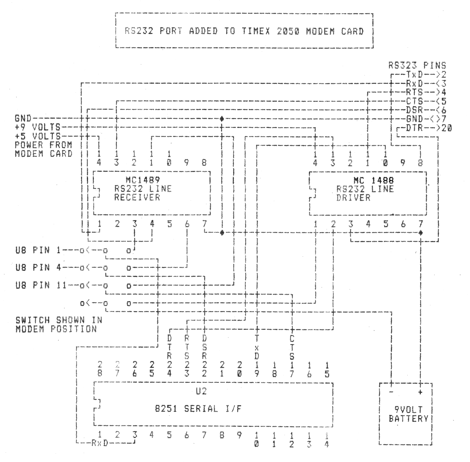
To add the RS232 Port to the 2050 Modem Card requires the addition of two IC’s, a four pole double throw switch and a 9 volt battery. Component mounting is not critical and I found that all parts can be mounted on a small PC board and piggy-backed on the top of the modem card. Select an area of the card where there are no modem components and drill two small holes using care not to cut any circuit traces on the board. A large enough area exists next to the 8251 (U2), this is where I mounted the piggy-back board. Next, using an Exacto-Knife, cut the copper circuits at the 8251 (U2) at pin 3 (RXD),pin 17 (CTS) and pin 22 (DSR). These are the three input lines to the 8251. Using a very fine point soldering iron, solder wires directly to the pins on the 8251 where the cuts were made. The other end of the wires are connected to the operating points of the four pole double throw switch as indicated in the wiring diagram. One side of the switch is then wired to the pins 1,4 and 11 on U8 and the other side is connected to the MC1489 RS232 line receiver. Next solder wires in the same manner to pins 19, 23 and 24 of the 8251 (U2). Connect the other end of the wires to the MC1488 RS232 line driver as shown in the diagram. The 8251 output signals are not switched and go the RS232 driver and modem. Add wires to the voltage points, I picked up the +5 volts at jumper W2 and +9 volts at the + side of C19. The ground connection can come from any of the large plated areas on the board. Finally, add the RS232 cable or connector. I used a 25 pin D-connector and the standard RS232 configuration. This will allow connection to a wide variety of devices such as external modems or serial interfaces on printers. Carefully check all connections for solder bridges or wire shorts.
Circuit Description
The MC1488 Driver and MC1489 Receiver provide a conversion from RS232 voltage levels (+15 to -15) to TTL levels (0 to +5). THree input and three output lines are connected to the 8251, four are control signals and two are data. To provide the minus RS232 level, a 9 volt battery is used. This will eliminate the necessity of an added power supply. The MC1489 line receiver requires a +5 volt source. This is connected to the modem card but the +5 volts is supplied by the Timex/Sinclair 2068 or T/S1000.
Checkout
The RS232 Port can be tested using a cable wrap method. At the RS232 connector, jumper RXD to TXD ,RTS to CTS and DTR to DSR. Load and run Mterm Smart II. Do a manual connect operation. The CONNECT prompt should appear. Then type characters in the FULL DUPLEX mode and the characters should echo to the screen as in half duplex mode only now the data is actually being transmitted and then received by the 8251. If all of these indications are observed then you are ready to connect to an RS232 device.
Operation
When using the RS232 Port, some of the modem circuits are left connected, therefore it is recommended that the phone cord be disconnected from the modem to prevent disruption of phone service. The 8251 must be initialized with software. When Mterm Smart II is started, the mode and control characters are sent to the 8251. The software then checks the conditions of the 8251 to see if the proper handshaking signals are present. The CTS line must be active for the for the 8251 to transmit data. This is an internal operation of the 8251 and cannot be bypassed. If your RS232 device is not capable of activating the CTS signal then jumper the RTS to CTS at the RS232 connector. The software will also check the state of the DSR line, if your serial device does not support this line then jumper DTR to DSR. Both software and device must be set at the same baud rate and communication parameters, such as 8 data bits, 1 stop bit and no parity.
Computer to computer communications
To use the RS232 to communicate directly with another computer bypassing modems, the RXD and TXD lines must be swapped at one end of the cable. This will make the TXD at computer A become the RXD at computer B and the RXD at computer A become TXD at computer B. Both computers must be set at the same baud rate and communication parameters.
NOTES ON OPERATION
WHEN NOT IN USE, S1 SHOULD BE SET TO MODEM TO PREVENT BATTERY DRAIN.
DICNONNECT PHONE LINE WHEN USING RS232 PORT.
DISCONNECT RS232 CABLE WHEN USING MODEM.