Authors
Publication
Pub Details
Date
Pages
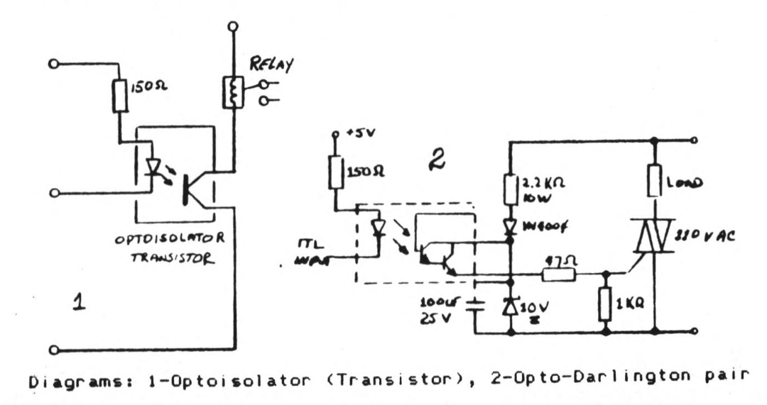
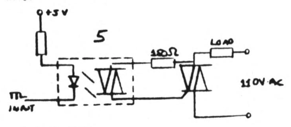
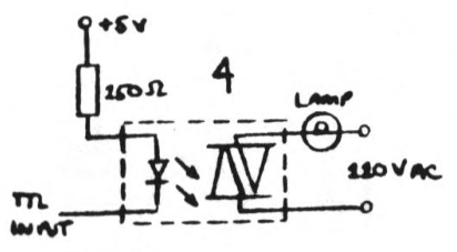
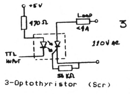
As stated in part 1, the outputs of the Port or latch can drive LEDs directly however, it would be preferred to isolate the output circuitry using optoisolaters. Refer to diagrams.
- An optotransistor with a Darlington pair and an LED can be used to drive a relay directly.
- An optothyristor can be used for controlling half wave AC line circuits such as, lights, pumps, valves and motors.
- Optodiac/Optotriac devices can be used to drive simple AC line circuits directly or with an additional Triac for heavier AC line applications.
The Port circuit can be connected to eight (8) opto devices since their is adequate power from the 5 volt computer power supply. External circuits driven from opto devices should contain their own power supply to prevent overloading the computer.
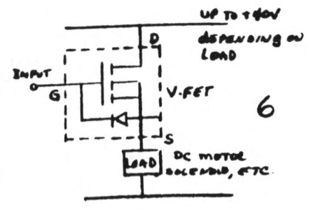
An alternative device which can be used safely as an interface between the computer, Out Port and external low-voltage DC circuitry is the V-FET or VMOS transistor. This is a high current Field Effect transistor (FET) that acts very well as a high current switch to operate DC motors such as in a train set control application or prehaps in Robotics and motors or servos. Thyristors and Triacs are AC devices which do not switch off under DC conditions, whereas the V-FET will switch on and off like a relay with the load being connected in the Drain or Source circuits in series with the transistor. A V-FET which can switch up to 2 amps is the VN46AF. This V-FET can use DC voltages up to 40V and is rated at 15 Watts.
The Out Port can be constructed using the PC board available from MAPLIN ELECTRONICS LTD; ENGLAND or from a section of multi-purpose perf board (ZEBRA) using point-to-point wiring or wire wrap techniques.
The relay board or opto drive board should be separate from the Port board since they will probably drive some sort of 110V AC devices. Double check all 110V connections for adequate insulation and/or shorts between the output circuitry.
Testing
Without the Port connected to the computer and with out any power present, check all connections with an ohmeter or continuity tester for shorts or open connections. If everything is OK, connect the Out Port to the computer and apply power. The computer should display the normal copywrite message at the bottom of your monitor screen — if not, shut off the computer immediately and recheck all wiring. If all is well, a voltmeter check from each latch output should read a logical 0; almost 0V.
Type in: OUT 31,255, then ENTER. All outputs should go high (logic 1), about 5 volts DC. Any relays connected to outputs will energize and opto devices will drive their respective loads.
To call each port (latch), use the following:
OUT 31,1........Latch 1
Out 31,2........Latch 2
Out 31,4........Latch 3
Out 31,8........Latch 4
Out 31,16.......Latch 5
OUT 31,32.......Latch 6
OUT 31,64.......Latch 7
OUT 31,128......Latch 8
If a combination of two or more Ports are required, use BINARY for the required number to activate multiple devices:
OUT 31,3........Latch 1 & 2
OUT 31,255......Latch 1 thru 8
OUT 31,7........Latch 1, 2, & 3
and so on..................Image Gallery