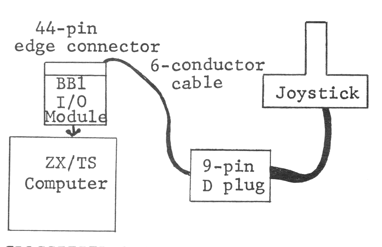
Keyboard scanning routines for joysticks given by Dave Straub in SYNTAX (Jun.82) and Dan Tandberg in SQ (Summer83) use only one code value at a time. I soon discovered I couldn’t move and shoot at once, nor move diagonally with any facility. I used some readily available hardware to create a full-function joystick compatible with my ZX81.
Expensive components–about $75–make up a big disadvantage to this system. Its great advantage–no modification of your computer, the joystick or the board–a totally modular approach. The computer stays hardware-independent of the joystick, you can use the BB-1 module for other jobs when not in use as a joystick port and you can also use the joystick with your Atari.
Contact-type joysticks (like Atari’s) use a ground line, four contacts for direction, and a fire button. Except for the pinout, Odyssey and Interact joysticks work the same way.
You wire the ground directly, so in order to independently sense the remaining functions, you need only five bit-sized inputs. I used five bits of the input port on Byte-Back‘s BB-1 I/O module to read the five button contacts. The BB-1 puts the 8 bits from its input port into memory address 32764 to store the joystick status exactly.
Just plug the BB-1 module into the back of your ZX/TS.
Make an adaptor and extension cord using Radio Shack connectors and ordinary 6-conductor telephone wire. Connect a 9-pin D-connector to a 44-pin edge connector to fit the input side of the BB-1 board.
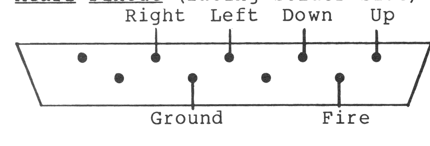
Pinout of Connections to BB-1
I/O  DATA  BINARY    DEC  DIRECTION
PIN  LINE  VALUE     VAL  COMMAND

19B  D7    01000000  128    Fire
11B  D4    00001000    8    Right
 9B  D3    00000100    4    Left
 7B  D2    00000010    2    Down
 4B  D1    00000001    1    Up
22B  Ground
     D5,6,8 Not Used
PEEK 32764 reveals joystick position. One position represents up to three moves. For example, with the stick pushed up and right and the fire button pushed, you read: 128(fire)+8(right)+1(up)=137.
Test the joystick by RUNning the following program. Move the joystick and the cursor follows. Press the fire button and a message prints on the screen.
  10 LET A=10
  20 LET B=10
  30 LET AW=PEEK 32764
  35 PRINT AT 1,1;"    "
  40 IF AW>=128 THEN GOTO 1000
  50 IF AW=1 OR AW=5 OR AW=9 THEN LET B=B-1
  60 IF AW=2 OR AW=6 OR AW=10 THEN LET B=B+1
  70 IF AW=4 OR AW=6 OR AW=5 THEN LET A=A-1
  80 IF AW=8 OR AW=9 OR AW=10 THEN LET A=A+1
 100 PRINT AT B,A;"[illegible]"
 120 GOTO 30
1000 REM **FIRE**
1010 PRINT AT 1,1;"FIRE"
1020 LET AW=AW-128
1030 GOTO 50
SYNTACTIC SUM: 25758 8K ROM
Parts Part # Vendor Price
Joystick CX-40 Atari $ 7.50
9-Pin D
Plug 276-1537 RS 1.99
9-Pin
Hood 276-1539 RS 2.19
44-pin Edge
Conn. 276-1551 RS 2.99
6 Conductor
Wire (8') 8778 Meshna 4.00
I/O Module BB-1 Byte-
Back 59.00