
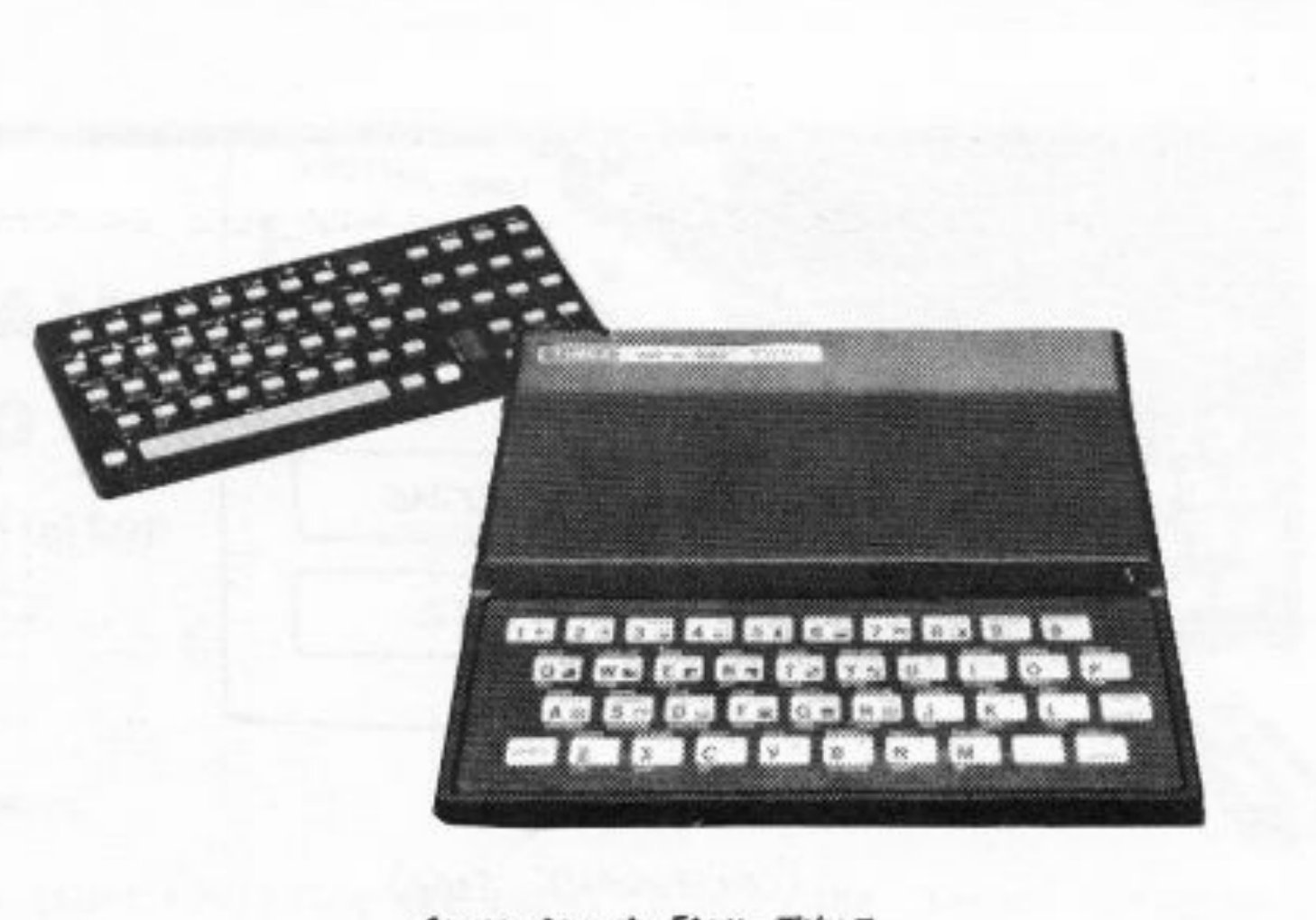
If you’re like me, you like to attach not only your memory pack, but also a modem, a printer, a joy-stick interface, an AC controller, and anything else that there is room for behind the computer. One of the big problems with this, especially if you have a matrix keyboard like the TI 99/4a that Radio Shack sells, attached off the main circuit board, are those “unexplained” crashes (the ones where you didn’t touch any peripherals on the back) or the external keyboard seems to “lock-up” on certain keys.
It’s caused by the “antenna effect”. The internal or external keyboard is directly connected to the CPU address bus through diodes, and acts like an antenna; picking up all kinds of noise such as that emitted from florescent lighting.
The diodes that are used to isolate the keyboard matrix from the address bus help, but just don’t do the job, especially when you add that all-important external keyboard to make your entry world a little easier. What is needed is some sort of buffer to completely isolate the address bus and provide plenty of “drive” to that nice external keyboard.
A 74HCT245 buss driver to the rescue! This driver not only provides the needed drive and isolation, but it also almost solders right in! Note that you can also use the slightly more inexpensive 74LS245, but it will use more power and dissipate more heat inside your computer.
First open your computer by removing the five screws on the bottom. When you do this, OBSERVE PROPER STATIC PRECAUTIONS! Work on an anti-static mat or sheet of aluminum foil. Keep your body in contact with the mat/foil, while handling your computer and the 74HCT245. Three of these screws are under the rubber feet. Take the back off and locate the two screws that hold the circuit board on to the top part of the case. Remove these two screws and CAREFULLY watch those two internal keyboard ribbon ribbon cables… and turn the Printed Circuit Board over.
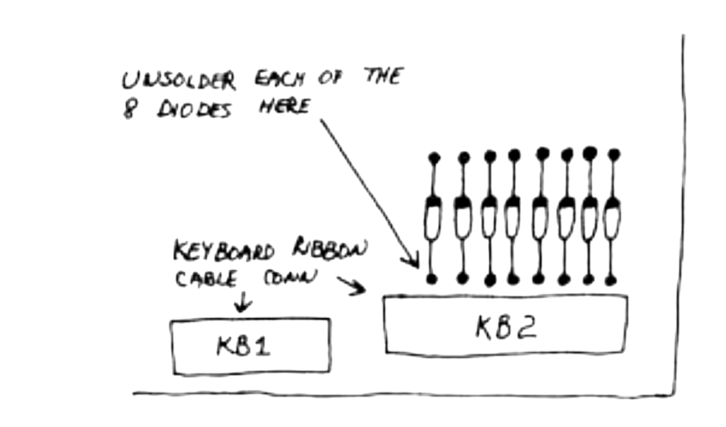
Using figure 1 locate the eight diodes just above the keyboard ribbon cables. Now using a pair of needle-nose pliers and a LOW WATTAGE (10 to 22 watts) soldering iron remove one side of each diode that is closest to the keyboard connector.
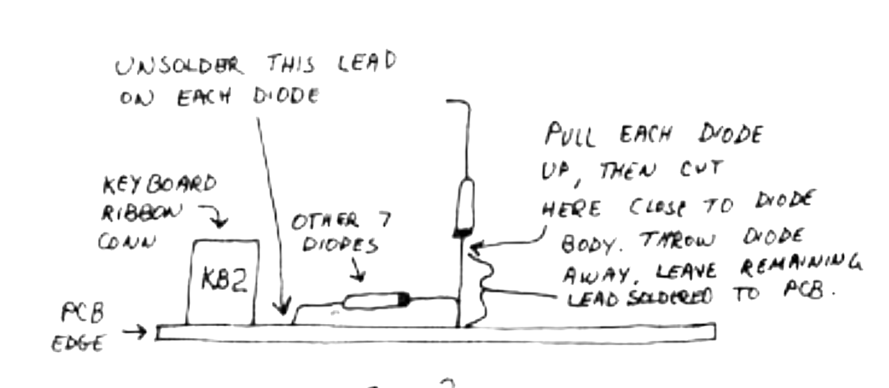
Using Figure 2, bend and then cut each of the eight diodes as shown.
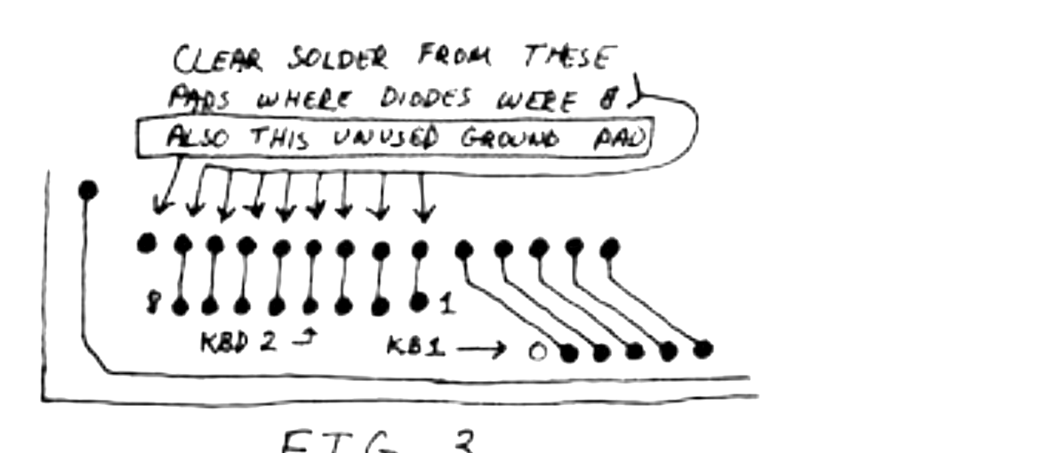
Next turn the PCB back over and working very carefully use a solder sucker or solder wick to remove the solder out of the pads closest to the keyboard connector and also from the pad just to the left of the left-most diode location. See figure 3.
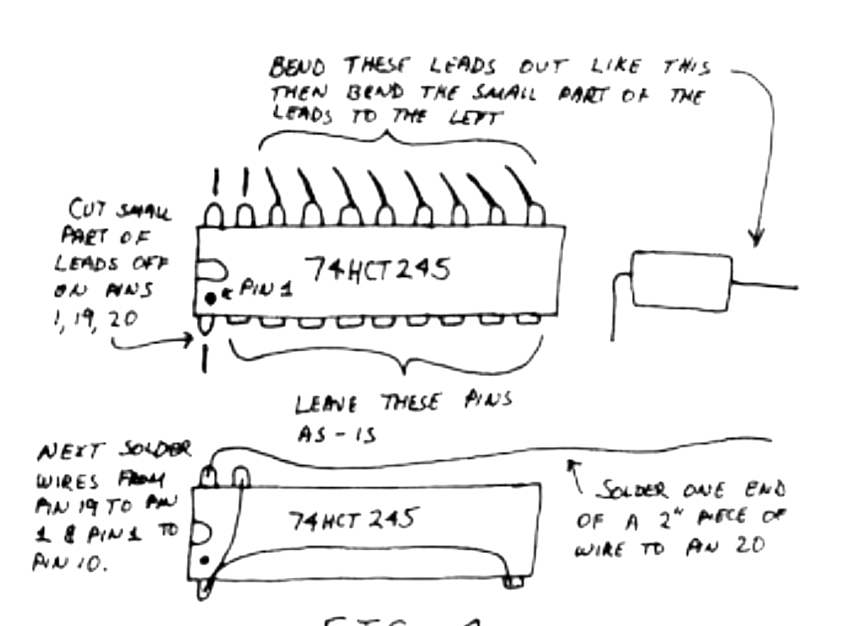
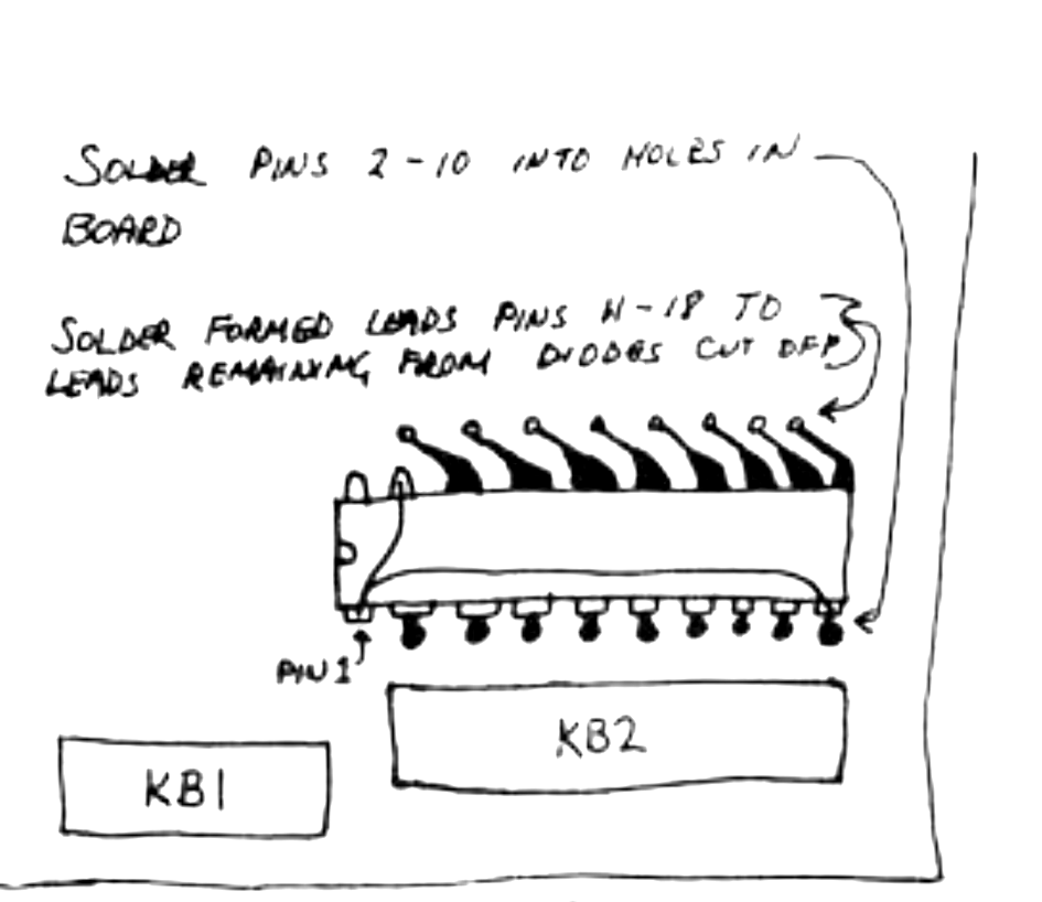
Now view figure 4 and form the leads of the 74HCT-245 as shown. Then add the three wires as shown in the same figure to the IC.
Now looking at the component side of the board, insert the IC so that pin 10 goes into the pad to the right and pins 2-9, go into the pads, where the diodes used to be. Check figure 5. Once you’re sure the IC is positioned correctly, solder pins 2-10 to the PCB, then solder pins 11-18 to the wire leads from the diodes.
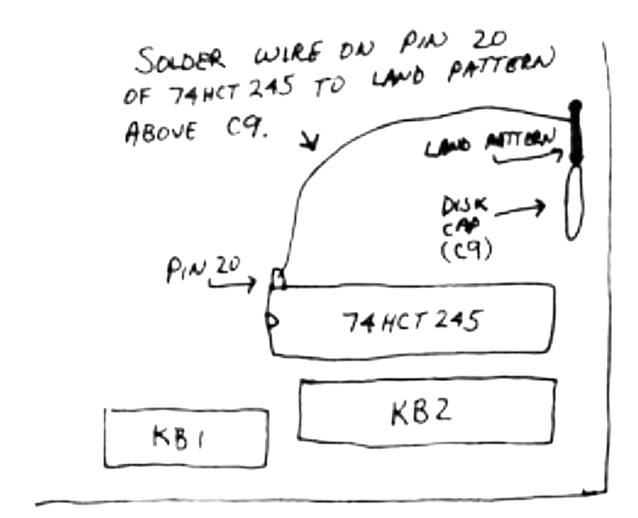
Lastly, using figure 6, solder the wire from pin 10 of the IC to the point shown in the same figure.
Re-assemble your computer, power up and try the keyboard. If all is well, add all those peripherals and enjoy. If your keyboard only partially works, check those internal ribbon cables and insure that they are not broken.