
A forum for people having problems with their 1000, 1500 and 2068. If you have any questions, send it to:
TS Communique
c/o Time Designs Magazine Co.
29722 Hult Road
Colton, OR 97017
I have a new 1985 Emerson 10″ portable color TV model EC12P. It has a video input jack and I am using it for a monitor for a 2068.
My problem is that I get ghost images on the left of the cursor and other letters. A printed full horizontal line of graphic squares will be color smeared on the left side and very dark on the right side of the line. The same with a vertical line. How do I correct this?
Earl Dunnington
Boynton Beach, FL
Dear Earl,
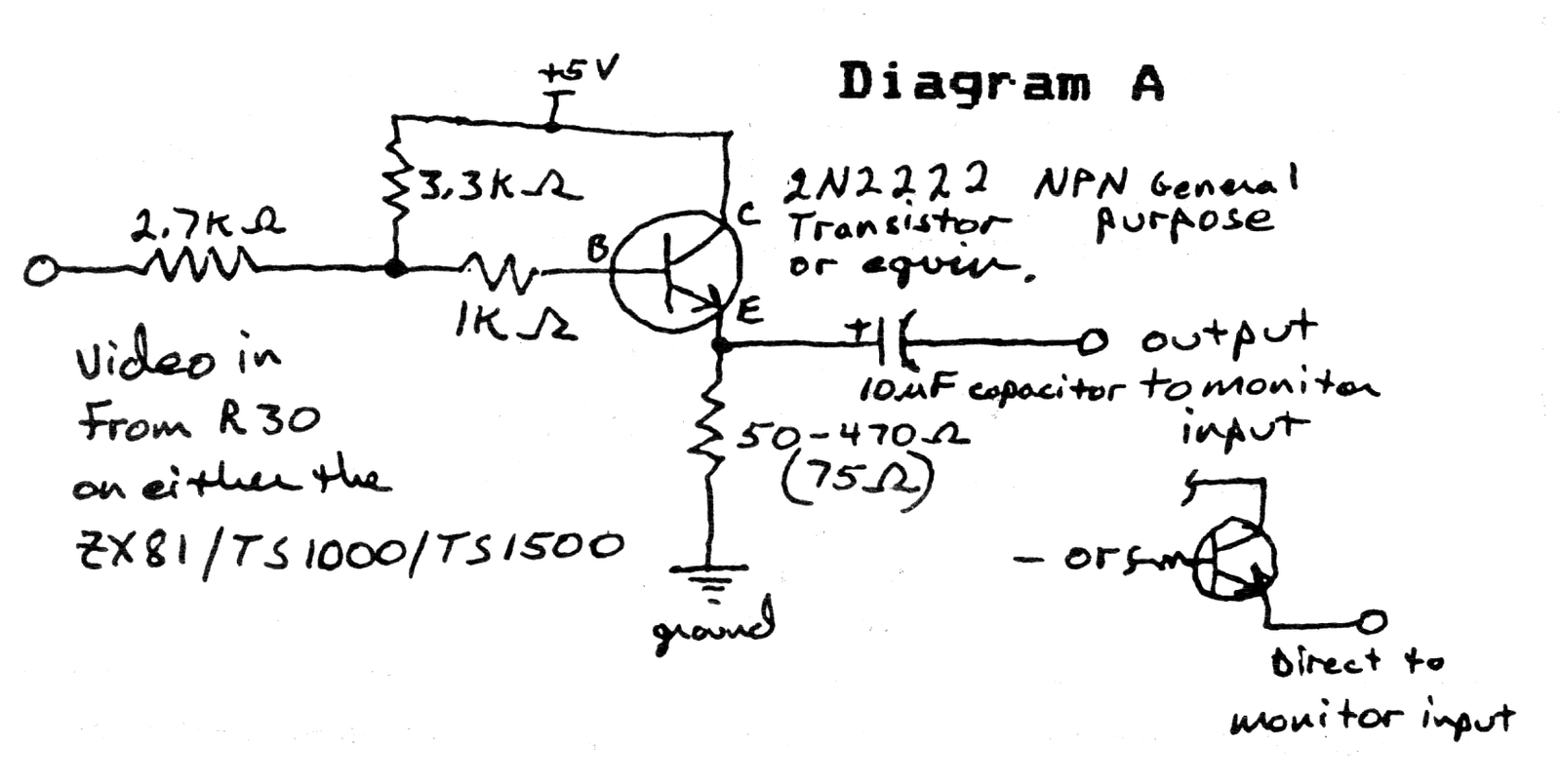
From the circuit diagram you supplied, the video input to your monitor is well buffered and DC isolated so the problem probably does not lie in the monitor, but in the 2068 (assuming of course that the TV in general works OK). Try adjusting the sync & white level (VR1) control next to the speaker inside the 2068. This should help some, but if not, try using a different source on the monitor such as a VCR. If that works OK, try changing the value of R67 in the 2068 (to the right of the big capacitors) which will change the output impedance (not known for being standard). Try values between 50 and 470 ohms. -Joe
I have attempted on several occasions with a low degree of success to adapt our ZX81 and TS1000 to our Magnavox monitor. I first tried Les Soloman‘s fix (Computers & Electronics, years ago) which amounted in tapping off the video to the RF modulator but that resulted in an unacceptably dark picture. Disconnecting the video input from the RF modulator gave only a marginally better display even with brightness and contrast at maximum.
I then proceeded through all of my SYNTAXs and in a very early issue found a circuit which used a 2N2222 transistor. Experimentation with that circuit ended by lowering the the input resistor to the base of the 2N2222 to 600 ohms to produce an acceptable display. However, I abandoned the project when I saw the display go extremly bright during the LOAD and SAVE operations – I was afraid of damage to the monitor.
Additionally, the 2N2222 circuit pulled so much current out of the video that it considerably narrowed the good-loading range from a cassette recorder. I was using QLOAD which was always touchier than standard equipment. I guess that my question is: Is there a simple under-the-hood circuit that you know of that will do the job and avoid the problems mentioned above?
John E. Juergens
Pacifica, CA
Dear John,
Your problem has occured with many a TS enthusiast trying to connect their computer to a monitor – In fact, it happens with many other computer lines as well. The problem stems (as above) from the differences in input impedance of different monitors. Some have high input impedance others have low (75 ohm) input impedance and some are even switchable. As far as the actual input circuit, some have DC block input (a capacitor in series with the input) and some do not.
The SYNTAX circuit (DEC ’81) was one of the better ones I have seen because it buffered the input and output of the circuit to protect LOAD/SAVE operations and provided the proper biasing of the transistor. The original circuit shown in the article just had the transistor and an emitter follower resistor as the output. With your monitor, you may want to try both of these output circuits. Try connecting the emitter of the transistor directly to the input of the monitor and also I would recommend using a 10 microFarad capacitor in the buffered version (to cut down on tearing and bending of characters) and try different value resistors from the emitter to ground in the range of 50 to 470 ohms. If the monitor is built right, 75 ohms should work the best. This circuit can also be used with the TS 1500. Also, don’t worry about the brighter screen in LOAd/SAVE operations as the monitor limits high level inputs. -Joe
In answer to Regis Giacobbe‘s request on how to save TOMAHAWK to Ramex disk (JAN/FEB ’88); TOMAHAWK’s basic loader program contains a machine code program embedded in a REM statement to set up the screen and load the machine code. The code which it reads from tape is headerless.
Section 4.2 of the Technical Manual describes what a header consists of. TOMAHAWK doesn’t use a header on the machine code block because the code embedded in the REM statement sets up the IX, DE, A, HL, and Flag registers with the necessary parameters to read the code block and calls the proper EXROM routine to read the code. After some “housekeeping” code, it then jumps into the TOMAHAWK game code and the game begins.
What many disk owners have done is to replace the final instruction which jumps into the game with a RET instruction which takes you back into BASIC. You can then SAVE the code with BASIC commands.
To SAVE TOMAHAWK, MERGE TOMAHAWK’s BASIC loader into the 2068. Add on to the program the lines:
10 ON ERR RESET
20 SAVE [your system syntax] "TOMAHAWK.SCR" SCREEN$
30 SAVE [your system syntax] "TOMAHAWK.COD" CODE
27584,37952
40 STOP
50 ON ERR GOTO 10
60 POKE 26839,201
70 GOTO 1
Type as a direct command: RUN 50. This will LOAD the non-standard screen, the game code, and SAVE them to your disk. You can then make up a new loader program to LOAD the screen and game code and start the game by deleting lines 1, 3 through 10, and 50 through 70. Adjust lines 20 to 40 as follows:
20 LOAD [your system syntax] "TOMAHAWK.SCR" SCREEN$
30 LOAD [your system syntax] "TOMAHAWK.COD" CODE
40 RAND USR 61184
Save this loader to auto start at line 2. In general, when dealing with a headerless code block, you must use a disassembler/monitor to examine the set up code. Look for a block of code statements which assign values to the following registers:
IX - This will be the loading address in
     RAM memory
DE - This is the length of the code block
HL - In TOMAHAWK, this was set to the address of the
     EXROM routine which does the tape read
A  - An FF stands for Data block
Carry Flag - Carry will be set for a load operation
In the case of TOMAHAWK, IX was 6BC0 hex, DE was 9440 hex, A was FF hex, Carry was set, and HL pointed to the EXROM tape read routine address. A call was then made to a routine which paged in the EXROM and jumped to the address pointed to by HL. Knowing this, it was easy to translate them into decimal values and make up the BASIC SAVE instructions.
Mike Finn
Philadelphia, PA
Dear Mike,
Thanks for the little on headerless program loading and for the info on converting TOMAHAWK to disk. -Joe
I own a TS 2068 and one Joystick. When playing games it works only in the left port. How can I get it to work in the right port? The right port is OK per a simple joystick test routine. Also, I use a Star Micronics STX-80 thermal printer with an AERCO Parallel Interface with my 2068 and it works great with TASWORD-TWO but I can not get it to print using TS/VU-CALC.
Arthur C. McDuffie
Keller, TX
Dear Arthur,
Most of the games that I have seen only “look” at the left joystick. Some do give you the option of using either joystick port, most do not. Unless its in BASIC, the only way you can change the joystick port is to know where the routine that looks at the joystick port resides in code and make the necessary changes. If its in BASIC, simply change it from STICK 1 to STICK 2.
VU-CALC would require you to use the print driver supplied with the AERCO interface. The program really needs to be modified to make full use of the larger printer, such as allowing more columns to be printed. I believe that there is a version that has been modified for full use of a full-sized printer. -Joe
In reply to Jim Powell‘s problem with the non-linearity of the TS 2040 printer, Timex is not the only one with this problem. I talked to a drafting teacher who works with IBM equipment and they have the same problem. Their solution is a software modification that corrects for the problem by multiplying the short axis by a correction factor. I’m not smart enough to do this but maybe someone out there is.
Don Balmer
Marquette, MI
Dear Don,
It seems to me that I read an article a few years ago on how to plot a (near) perfect circle on the screen using a correction factor. I am sure this same method could be used to print to the printer as well. Does anyone out there remember that article? I was not able to locate it. -Joe
When I hook my QL up to my Sears TV/Monitor/RGB and use it in the monitor mode (F1) the picture will not hold steady, it rolls. However, it works fine in TV mode (minus the 64 scan lines). Is there a means to remedy this without having to own two seperate monitors for each computer?
Michael E. Carver
Portland, OR
Dear Michael,
You hit the nail on the head when you said the 64 scan lines were gone! In essence, the vertical timing is changed and so the monitor won’t lock up until the vertical hold is adjusted on the monitor to correct for the change. On my Sears monitor I am able to get a nice steady picture after adjusting the vertical hold in both TV and monitor mode although the control is more sensitive when in monitor mode. -Joe
My 2068 will no longer output color to either a monitor (Commodore 1802) or color TV. I’ve tried adjusting VR1, VR2, and VR3. While my display does seem to change shades of gray, its still not color. I’m going to try replacing the LM1889 chip (it’s only $1.29) to see if that works. I’m also going to replace the 78L12 with a 78M12 suggested for the RGB interface to try and “clean up my screen” When I get an RGB monitor.
I would also like to hook up a jack that puts out both BEEP & SOUND. I’d also like information on the hardware required for bank switching or building an external RAM expansion.
Don Witfanood
USS Horne (CG-30)
Dear Don,
You need to adjust the capacitor inside the RF modulator (metal can at left rear of unit) for best color lock. Since you turned the other controls, you will need to play around with different settings until best results are obtained. If you still don’t get color, you may have to replace the LM1889.
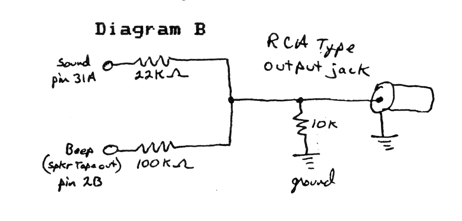
The BEEP & SOUND can be picked off the rear edge connector and sent to a seperate jack which can then be connected to one of those $12 audio amplifiers that Radio Shack sells. BEEP can be found on pin 2B (component side) and SOUND can be found on pin 31A (component side). Use 100K ohms in series with the BEEP connection and 22k ohms in series with the SOUND connection and the junction of these two to ground as shown. Watch for RAM expansion in the next issue. -Joe
I hope there is some help for this problem even though it’s not exactly a Timex product. I have an A & J Microdrive. The driver relocation instructions with the unit are wrong in some way. The address for the “TABLE” is given at 62254 and 26255 which is a typographical error. In any case, the address I find is 8669 which I believe is wrong. I don’t know enough about the addressing to solve this problem. Many programs ask to relocate the driver at 64000 or above. Is any help available to relocate the driver?
E. W. (Bud) Arbtin
Shawnee, KS
Dear Bud,
I believe the table you are looking for is at 26703 and 26704 which is the address of the printer output routine. At least thats the one thats changed for programs like Tasword II and Profile. for the 2040 printer this contains address 1280 which is the TS printer routine in ROM. This can be changed to address 64000 by poking 26703 with 0 and 26704 with 250 (0 + 256 * 250 = 64000). A & J may have an intermediate “TABLE” of some sort but the POKEs above should do it if thats the actual start of the printing routine. I’m really not that familiar with A & J’s printer interface. -Joe