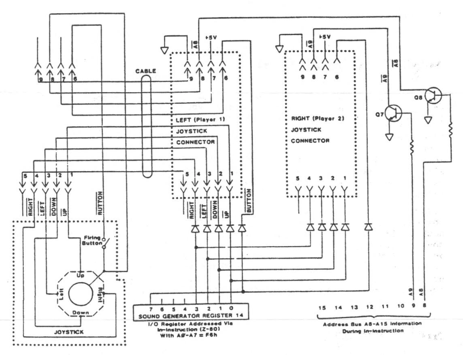
The two joysticks are controlled via Register 14 (I/O Port A) of the Programmable Sound Generator Chip (see Sections 2.1.6 and 2.1.7). Address and respectively. data are passed via Ports 0F5H and 0F6H The joysticks are read by first addressing Register 14 in the PSG by writing a 14 (OEH) to Port 0F5H. data is then read by executing an The IN from Port OF6H, having the port address in 280 Register C and the joystick (player) number in Register B (number = 1 or 2). Note that PSG Register 7, Bit 6 is assumed to be zero, enabling I/O Port A for input. If you ever use I/O Port A for I/0 Port A for output (R7, B6=1), you will want to clear Bit 6 prior to any input operation.
Sample routine:
GETJOY LD A,OEh         Load A=14
       OUT A,(0F5h)     Address the joystick port
       LD B,playerno
       LD C,0F6h        Data port address C
       IN A,(C)         Joystick data to A
       CPL              Complement to high active
       AND 8Fh          Get significant bits
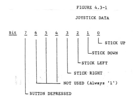
The data read is LOW ACTIVE, i.e. all bits = 1 (byte=FFH) when the stick is at center and the button is not depressed. Figure 4.3-1 shows the interpretation of the data byte.
Note
This is reprinted from the Technical Manual.
Image Gallery