November 1992
Several meetings ago, Jeff Taylor demoed a Zebra joystick interface for the ZX81. At that time, several people expressed an interest in making one, so I looked through my files for a circuit that I could use in a construction article. I found one written up in the June 1984 issue of Electronics Today International and changed one of the chips and added the edge connector to mount the interface on the back of the ZX81. The interface is I/O mapped to Port 31, making it compatible with the 2068 to play Spectrum and 2068 programs that use a Kempston Joystick system. It will also work with a Commodore 1351 mouse in joystick mode.
THE HARDWARE
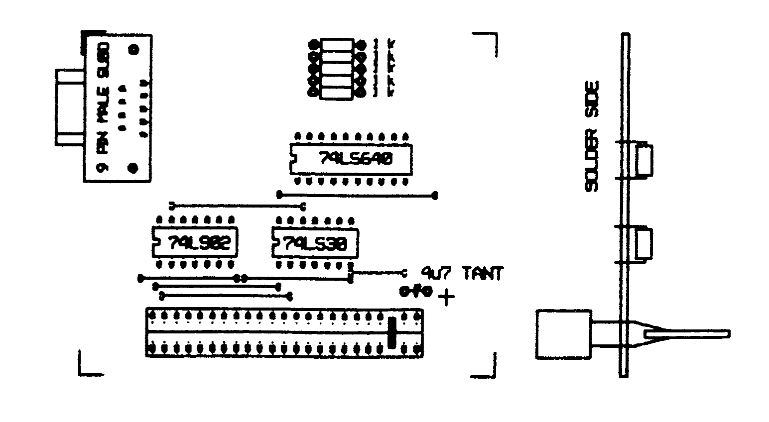
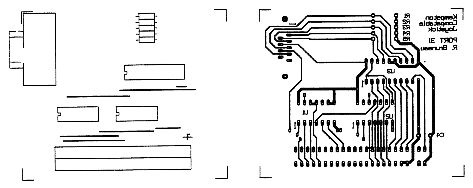
As with past projects, I have provided a PCB mask to be photocopied onto TEC 200 mylar film for transferring to a blank board. Load the components as shown on the overlay, being careful to install the sockets and capacitor correctly. The edge connector is located on the copper side of the board, with the components and extender on the side facing away from the computer. Check for poor solder joints and jumps between traces and clean any that are suspect. Before you install the ICs on the board, plug the assembly onto the rear edge connector of your computer, turn it on, and confirm that the computer initializes properly. If it doesn’t, quickly shut off the machine and check your work again.
TESTING
If you have access to a 2068, testing is simple. Enter the following program and run it with a joystick plugged in.
1 PRINT AT 15,10; IN 31
2 PAUSE 5
3 PRINT AT 15,10;"  "
4 GOTO 1
For the ZX81, a short machine code program must be entered as follows:
1 REM 123456
2 FOR X=16514 TO 16519
3 INPUT A
4 POKE X,A
5 NEXT X
6 CLS
7 PRINT AT 15,10; USR 16514
8 PRINT AT 15,10;"  "
9 GOTO 7
The data requested in line 3 is:
219, 31, 6, 0, 79, 201If the interface is working correctly, a 0 will be printed in the middle of the screen. The number should change as you move the joystick or press the fire button. The number printed will correspond with those shown below. Note that holding the stick in the corners will give you a sum of the vertical and horizontal values. For example, with the stick in the top right corner a 9 is printed on the screen, holding down the fire button at the same time increases the number by 16 (DOWN + RIGHT + FIRE = 8 + 1 + 16 = 25)
ACTION    RESULT PRINTED    BIT
Right            1           0
Left             2           1
Up               4           2
Down             8           3
Fire            16           4
For those who have a copy of FIGHT SIMULATOR, here are some pokes to adapt it to allow the use of a joystick. Use a FOR/NEXT loop to enter the code. We will provide additional program pokes in future issues of this newsletter.
ADD.    DEC. CODE       MNEMONIC
17316   205, 247, 75    Call 19447
Write code to #2 REM statement with 50 Xs.
ADD.    CODE            LABEL   MNEMONIC
19447   219, 31                 IN A, 31
        254, 0                  CP 0
        40, 32                  JR Z, EXIT
        254, 4                  CP 4
        32, 4                   JRNZ, DOWN
        33, 239, 239            LD HL, 239, 239
        201                     RET
        254, 8          DOWN    CP 8
        32, 4                   JRNZ, LEFT
        33, 239, 223            LD HL, 223, 239
        201                     RET
        254, 2          LEFT    CP 2
        32, 4                   JRNZ, RIGHT
        33, 247, 223            LD HL, 223, 247
        201                     RET
        254, 1          RIGHT   CP 1
        32, 4                   JRNZ, EXIT
        33, 239, 247            LD HL, 247, 239
        201                     RET
        205, 187, 2     EXIT    CALL KSCAN
        201                     RET
COMPONENT LIST
U1     74LS02
U2     74LS30
U3     74LS640
C1     4u7 Tantalum Capacitor
R1-R5  1K 1/4 watt Resistor
P1     Male 9-pin Subd Socket
P2     ZX81 Edge connector and extender
Misc.  2-14 pin dip, 1-20 pin dip, Solid wire for jumpers
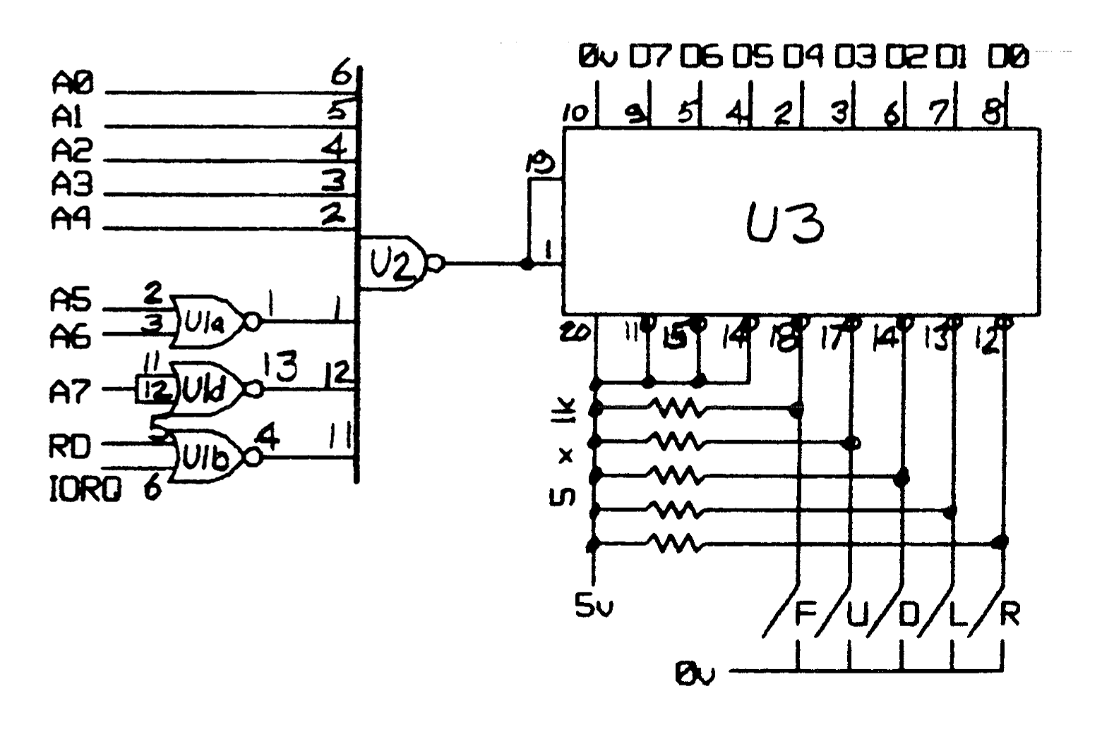
CIRCUIT DIAGRAM
COMPONENT PLACEMENT