
Model Plane Designer is an interactive radio-control aircraft design tool that renders scaled top, side, and front-view line drawings of a model airplane based on user-supplied measurements. The program accepts up to 25 parameters covering fuselage geometry, wing planform (including polyhedral/constant-chord sections), stabilizer, and tail fin, then computes the center of gravity, aspect ratios, wing loading, and surface area percentages. Four built-in presets (trainer, glider, and gullwing) are provided via preset DATA at line 30 and a separate block starting at line 50. An ON ERR loop at lines 2025 and 2030 automatically reduces the drawing scale factor by 3–5% and retries up to ten times if a PLOT or DRAW coordinate falls outside the screen boundary, ensuring the drawing fits without crashing.
Program Structure
The program is organized into a clear set of functional blocks separated by line-number ranges:
| Line Range | Purpose |
|---|---|
| 10–70 | Entry point, preset loaders (trainer via DATA, glider via assignment block) |
| 75–325 | Interactive parameter input routine (25 variables) |
| 330–625 | Top-view drawing engine |
| 635–795 | Side-view drawing engine |
| 800–840 | Main menu dispatcher |
| 905–995 | Wing sub-menu (view and edit) |
| 1005–1095 | Fuselage sub-menu |
| 1105–1190 | Stabilizer sub-menu |
| 1200–1290 | Tail fin sub-menu |
| 1300–1505 | Printed specifications output |
| 1510–1520 | Subroutine: pause and optional COPY printout |
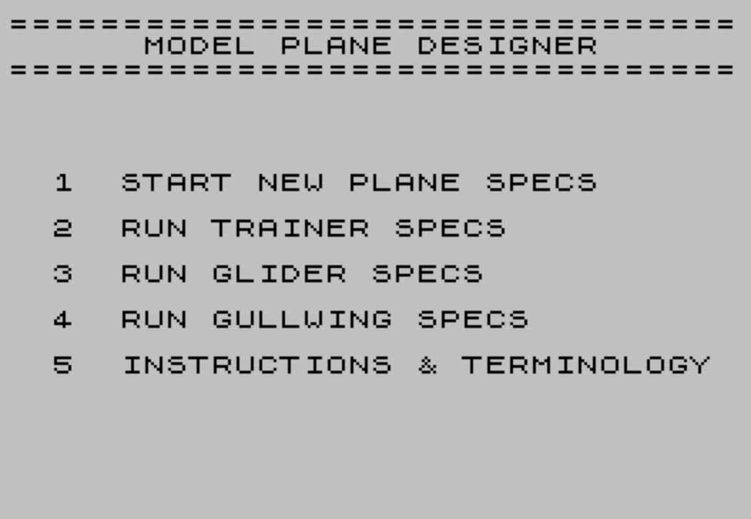
| 1525–1565 | Top-level start menu |
| 1570–1895 | Eight-page instruction and terminology display |
| 1900–2010 | Front-view drawing subroutine |
| 2025–2075 | Error recovery and wing-side-view helper subroutine |
| 2080 | SAVE with auto-run |
Preset Aircraft Configurations
The program provides four preset configurations selectable from the opening menu. The trainer preset (option 2 and the gullwing base, option 4) uses a RESTORE/READ pair at lines 20–25 pulling from the 25-element DATA statement at line 30. The gullwing variant then immediately overrides seven of those values at line 40 before jumping to line 330. The glider preset (option 3) at lines 50–70 assigns all 25 variables directly without using DATA, which avoids needing a second DATA block.
Drawing Engine and Scaling
All three views (top, side, front) are drawn using PLOT/DRAW pairs with a common scale factor p computed from the total fuselage length fl and the available screen pixels. The top-view scale is initialized at line 360 as 170/fl, then clamped at line 365 so the wingspan never exceeds 250 pixels. The side view at line 655 uses 230/fl. The front view at line 1900 independently scales on wingspan as 250/ws.
The scale factor p is a floating-point multiplier applied to every measurement before it is passed to PLOT or DRAW, so all geometry is proportionally correct regardless of the actual dimensions entered.
Automatic Error Recovery and Retry Loop
A distinctive technique is used to handle cases where computed coordinates fall outside the displayable screen area. At line 375, ON ERR GO TO 2025 arms a handler before the top-view drawing begins. Line 410 increments a time counter, and line 415 checks whether ten failed attempts have occurred; if so, ON ERR RESET disarms the handler and lets the error propagate so the user can break to the menu. On each failed attempt, line 2025 reduces p by 3% (p=p*.97), clears the screen, re-arms the handler, and jumps back to line 400 to retry the entire drawing. The side view uses a parallel handler at lines 635 and 2030 that reduces p by 5% per attempt.
Menu Dispatch Technique
The main menu at line 840 uses the idiom GO TO VAL "(800+100*(VAL q$))" to jump to sub-menus at lines 900, 1000, 1100, 1200, and 1300 based on the digit key pressed (1–5). This avoids a chain of IF statements and is a well-known memory-saving trick. Keys 6 and 7 are handled by explicit IF checks at lines 830–835 before the dispatch.
Sub-Menu Edit Pattern
Each of the four sub-menus (wing, fuselage, stabilizer, fin) follows an identical pattern: display all current values in a numbered list, wait for a keypress with PAUSE 0/INKEY$, flash the selected line with FLASH 1, INPUT a new value as a string, assign it with VAL q$, and redisplay the updated value in place using PRINT AT. The use of VAL q$ on the input means the user can enter arithmetic expressions as well as plain numbers.
Center of Gravity and Area Calculations
The CG calculation at lines 1335–1365 handles both simple tapered and mixed constant-chord/tapered planforms. For a pure tapered wing, cg = (wr+wt)/2/3 + wsw/2 (line 1350). For a wing with a constant-chord inboard section, a weighted average between the constant-chord CG (cgcc = wr/3) and the full-wing CG is computed using the ratio of the tapered portion’s area to total area (lines 1335–1359). Wing area is the sum of the rectangular inboard area and the trapezoidal outboard area. The CG range displayed to the user is cg*0.8 to cg, representing a recommended 20% forward safety margin.
Aspect ratio for both wing and stabilizer is computed as span divided by root chord, which is an approximation (true aspect ratio uses mean chord), but is common practice in hobbyist design tools. Stabilizer area as a percentage of wing area and vertical fin area are also reported.
Wing Dihedral Side-View Subroutine
The subroutine at lines 2035–2075 handles the wing cross-section in the side view for both high-wing and low-wing configurations. It is called conditionally at lines 685 and 720 depending on the wh variable. A special case at line 2035 handles the zero-dihedral, zero-constant-chord scenario by drawing a simple flat line, avoiding a degenerate DRAW with zero displacement that could cause an error.
Notable Bugs and Anomalies
- The top-view right-wing drawing at line 570 adds a hard-coded
+1pixel offset ((x+fw/2)*p+1) that is not applied to the left wing, creating a very slight asymmetry in the rendered image. - Line 1415 uses the string Boolean idiom
("HIGH WING" AND wh=1)+("LOW WING" AND wh=2)to select and print the appropriate label — a correct and idiomatic Sinclair BASIC technique. - The
p$="4"gullwing branch at line 40 setsntw=8andtets=13but does not alterws,ss, or other geometry, so the gullwing is effectively a trainer with different dihedral and chord values rather than a fully distinct airframe.
Image Gallery
Source Code
   10 REM by CARL GREEN, EAST LIVERPOOL, OHIO
   15 GO TO 1525
   20 RESTORE
   25 READ oz,ntw,btn,btt,fw,tets,stett,wr,wt,cc,ccd,di,ws,wsw,wh,sr,st,ss,sw,sh,fr,fh,ft,fs,fpf
   30 DATA 64,5,1,1,2.5,16,-1,9,6,0,0,3.5,57,3,1,7,6,21,1,0,5.5,6,5.5,1.5,0
   40 IF p$="4" THEN LET cc=16:LET ccd=-2:LET di=1:LET ft=3:LET wh=2:LET ntw=8:LET tets=13
   45 GO TO 330
   50 LET oz=84:LET ntw=12:LET btn=0:LET btt=0:LET fw=2:LET tets=20:LET stett=-1
   55 LET wr=10.5:LET wt=6.5:LET cc=56:LET ccd=1:LET di=6:LET ws=120:LET wsw=4:LET wh=1
   60 LET sr=6:LET st=4:LET ss=28:LET sw=1:LET sh=8
   65 LET fr=8:LET fh=11.5:LET ft=5:LET fs=1.5:LET fpf=3.5
   70 GO TO 330
   75 PRINT "MODEL WEIGHT (oz) ";
   80 INPUT oz:PRINT oz
   85 PRINT "NOSE TO WING L.E.";
   90 INPUT ntw:PRINT ntw
   95 PRINT "DISTANCE BETWEEN LOWEST POINT OFFUSELAGE TO HEIGHT OF NOSE ";
  100 INPUT btn:PRINT btn
  105 PRINT "DISTANCE BETWEEN LOWEST POINT OFFUSELAGE TO HEIGHT OF TAIL ";
  110 INPUT btt:PRINT btt
  115 PRINT "FUSELAGE WIDTH ";
  120 INPUT fw:PRINT fw
  125 PRINT "WING T.E. TO STABELIZER L.E. ";
  130 INPUT tets:PRINT tets
  135 PRINT "FUSELAGE PAST STABELIZER T.E.   neg. no. puts stab. past        fuselage ";
  140 INPUT stett:PRINT stett
  145 PRINT "WING ROOT ";
  150 INPUT wr:PRINT wr
  155 PRINT "WING TIP ";
  160 INPUT wt:PRINT wt
  165 PRINT "CONSTANT CHORD SPAN use this if you have a constant chord and a tapered section, otherwise      enter '0' ";
  170 INPUT cc:PRINT cc
  175 IF cc<2 THEN LET ccd=0:GO TO 190
  180 PRINT "DIHEDEDRAL OF CONSTANT CHORD    ";
  185 INPUT ccd:PRINT ccd
  190 PRINT "TOTAL DIHEDRAL AT TIP OF WING  ";
  195 INPUT di:PRINT di
  200 PRINT "TOTAL WING SPAN ";
  205 INPUT ws:PRINT ws
  210 PRINT "WING SWEEP  measured from root  l.e. to tip l.e.  ";
  215 INPUT wsw:PRINT wsw
  220 PRINT "HIGH WING INPUT (1)             LOW  WING INPUT (2) ";
  225 INPUT wh:PRINT wh
  230 PRINT "STABILIZER ROOT ";
  235 INPUT sr:PRINT sr
  240 PRINT "STABELIZER TIP ";
  245 INPUT st:PRINT st
  250 PRINT "TOTAL STABELIZER SPAN ";
  255 INPUT ss:PRINT ss
  260 PRINT "STABELIZER SWEEP ";
  265 INPUT sw:PRINT sw
  270 PRINT "STABELIZER ABOVE FUSE (for 'T'  or high tails) ";
  275 INPUT sh:PRINT sh
  280 PRINT "FIN ROOT ";
  285 INPUT fr:PRINT fr
  290 PRINT "FIN TIP ";
  295 INPUT ft:PRINT ft
  300 PRINT "FIN HEIGHT ";
  305 INPUT fh:PRINT fh
  310 PRINT "SWEEP OF FIN AT TIP ";
  315 INPUT fs:PRINT fs
  320 PRINT "FIN OR RUDDER PAST FUSELAGE     (neg. no. puts fin farther      forward on fuselage) ";
  325 INPUT fpf:PRINT fpf
  330 LET cg=(wr+wt)/2/3+wsw/2
  335 CLS
  340 LET time=0
  345 LET fl=ntw+tets+stett+wr+sr
  350 LET x=ws/2
  355 LET y=175
  360 LET p=170/fl
  365 IF ws*p >=250 THEN LET p=250/ws
  370 IF cc >=(ws-5) THEN LET cc=0
  375 ON ERR GO TO 2025
  380 PRINT AT 0,22;"C.G. at"
  385 PLOT 245,170
  390 DRAW 2,2:DRAW -2,2:DRAW -2,-2:DRAW 2,-2
  395 REM <<fuselage left>>
  400 PLOT x*p,y
  405 PRINT AT 0,0;"TOP VIEW"
  410 LET time=time+1
  415 IF time >=10 THEN ON ERR RESET
  420 DRAW -fw/8*p,0
  425 DRAW -fw/2*p+fw/8*p,-ntw*p
  430 DRAW 0,-wr*p
  435 DRAW fw/4*p,-tets*p
  440 REM <<left wing>>
  445 PLOT p*(x-fw/2),y-ntw*p
  450 IF cc>fw THEN DRAW (fw-cc)/2*p,0
  455 DRAW (cc+fw-ws)/2*p,-wsw*p
  460 DRAW 0,-wt*p
  465 DRAW p*(ws-cc-fw)/2,(-wr+wt+wsw)*p
  470 DRAW (cc-fw)/2*p,0
  475 REM <<left stab>>
  480 PLOT x*p,y-fl*p
  485 DRAW -fw/4*p,sr*p+stett*p
  490 DRAW -ss*p/2,-sw*p
  495 DRAW 0,-st*p
  500 DRAW p*ss/2+(fw/4*p),(-sr+st+sw)*p
  505 REM <<right fuse.>>
  510 PLOT x*p,y
  515 DRAW fw/8*p,0
  520 DRAW fw/2*p-fw/8*p,-ntw*p
  525 DRAW 0,-wr*p
  530 DRAW -fw/4*p,-tets*p
  535 REM <<right stab>>
  540 PLOT x*p,y-fl*p
  545 DRAW fw/4*p,(sr+stett)*p
  550 DRAW ss/2*p,-sw*p
  555 DRAW 0,-st*p
  560 DRAW -ss/2*p-fw/4*p,(-sr+st+sw)*p
  565 REM <<right wing>>
  570 PLOT (x+fw/2)*p+1,y-ntw*p
  575 IF cc>fw THEN DRAW (cc-fw)/2*p,0
  580 DRAW (-cc-fw+ws)/2*p,-wsw*p
  585 DRAW 0,-wt*p
  590 DRAW (fw-ws+cc)/2*p,(-wr+wt+wsw)*p
  595 DRAW (fw-cc)/2*p,0
  600 PLOT x*p,y-(fl+fpf)*p
  605 DRAW 0,fr*p
  610 DRAW 0,-(fs+ft)*p
  615 PLOT x*p,y-(ntw+cg)*p
  620 DRAW 2,2:DRAW -2,2:DRAW -2,-2:DRAW 2,-2
  625 ON ERR RESET
  630 GO SUB 1510
  635 CLS :ON ERR GO TO 2030
  640 PRINT AT 0,22;"C.G. at"
  645 PLOT 245,170
  650 DRAW 2,2:DRAW -2,2:DRAW -2,-2:DRAW 2,-2
  655 LET p=230/fl:LET y=170-(fh+fw)*p:LET x=254
  660 PLOT x,y
  665 PRINT AT 0,0;"SIDE VIEW"
  670 REM <<fuse bottom>>
  675 DRAW 0,-2
  680 DRAW -ntw*p,-btn*p
  685 IF wh=2 THEN GO SUB 2035
  690 DRAW -wr*p,0
  695 DRAW (wr+ntw-fl)*p,btt*p
  700 DRAW 0,2
  705 REM <<fuse top>>
  710 PLOT x,y
  715 DRAW -ntw*p,(fw-btn)*p
  720 IF wh=1 THEN GO SUB 2035
  725 DRAW -wr*p,0
  730 DRAW (fr+wr+ntw-fl-fpf)*p,(btt-fw)*p
  735 REM <<fin>>
  740 DRAW -fs*p,fh*p
  745 DRAW -ft*p,0
  750 DRAW (fs+ft-fr)*p,-fh*p
  755 DRAW fr*p,0
  760 PLOT x-(ntw+wr+tets+sr)*p,y+(sh+btt-btn)*p
  765 DRAW sr*p,0
  770 DRAW 0,1:DRAW -(sw+st)*p,0
  775 PLOT x-(ntw+cg)*p,y
  780 DRAW 2,2:DRAW -2,2:DRAW -2,-2:DRAW 2,-2
  785 ON ERR RESET
  790 GO SUB 1900
  795 GO SUB 1510
  800 CLS
  805 LET time=0
  810 PRINT "           MAIN MENU",,,,,,,,,"   1 WING",,,,"   2 FUSELAGE",,,,"   3 STABILAZER",,,,"   4 TAIL FIN",,,,"   5 PRINT OUT SPECS",,,"   6 START PROGRAM OVER",,,"   7 STOP PROGRAM"
  815 PRINT AT 21,8;"ENTER NO.(1-7) "
  820 PAUSE 0:LET q$= INKEY$
  825 IF CODE q$>55 OR CODE q$<49 THEN GO TO 820
  830 IF q$="6" THEN GO TO 1525
  835 IF q$="7" THEN CLS :PRINT AT 10,10;"OK TO RUN":STOP
  840 GO TO VAL "(800+100*(VAL q$))"
  905 CLS :PRINT "             WING:",,,"1 ROOT",wr,,,"2 TIP",wt,,,"3 TOTAL SPAN",ws,,,"4 CC SPAN",cc,,,"5 CC DIHEDRAL",ccd,,,"6 TOTAL DIHED.",di,,,"7 SWEEP AT L.E.",wsw,,,"8 HIGH(1) LOW(2)";wh,,,"9 MAIN MENU",,,,"0 RE-DRAW"
  910 PAUSE 0:LET q$= INKEY$
  915 IF CODE q$>57 OR CODE q$<48 THEN GO TO 910
  920 LET q= VAL q$
  925 IF q=9 THEN GO TO 800
  930 IF q=0 THEN CLS :GO TO 330
  935 PRINT FLASH 1; AT q*2,0;q
  940 INPUT "CHANGE TO WHAT ? ";q$
  945 IF q$="" THEN GO TO 940
  950 IF q=1 THEN LET wr= VAL q$
  955 IF q=2 THEN LET wt= VAL q$
  960 IF q=3 THEN LET ws= VAL q$
  965 IF q=4 THEN LET cc= VAL q$
  970 IF q=5 THEN LET ccd= VAL q$
  975 IF q=6 THEN LET di= VAL q$
  980 IF q=7 THEN LET wsw= VAL q$
  985 IF q=8 THEN LET wh= VAL q$
  990 PRINT AT q*2,0;q; AT q*2,16;q$;"  "
  995 GO TO 910
 1005 CLS :PRINT "        FUSELAGE",,,"1 WIDTH",fw,,,"2 NOSE TO WING  ";ntw,,,"3 TE TO STAB LE",tets,,,"4 NOSE HEIGHT",btn,,,"5 TAIL HEIGHT",btt,,,"6 STAB TO TAIL",stett,,,"7 WEIGHT IN OZ. ";oz,,,"8 MAIN MENU",,,,"0 RE-DRAW"
 1010 PAUSE 0:LET q$= INKEY$
 1015 IF CODE q$>57 OR CODE q$<48 THEN GO TO 1010
 1020 LET q= VAL q$
 1025 IF q=8 THEN GO TO 800
 1030 IF q=9 THEN GO TO 1010
 1035 IF q=0 THEN CLS :GO TO 330
 1040 FLASH 1:PRINT AT q*2,0;q:FLASH 0
 1045 INPUT "CHANGE TO WHAT ? ";q$
 1050 IF q$="" THEN GO TO 1045
 1055 IF q=1 THEN LET fw= VAL q$
 1060 IF q=2 THEN LET ntw= VAL q$
 1065 IF q=3 THEN LET tets= VAL q$
 1070 IF q=4 THEN LET btn= VAL q$
 1075 IF q=5 THEN LET btt= VAL q$
 1080 IF q=6 THEN LET stett= VAL q$
 1085 IF q=7 THEN LET oz= VAL q$
 1090 PRINT AT q*2,0;q; AT q*2,16;q$;"  "
 1095 GO TO 1010
 1105 CLS
 1110 PRINT "         STABALIZER",,,"1 ROOT",sr,,,"2 TIP",st,,,"3 SPAN",ss,,,"4 SWEEP AT L.E.",sw,,,"5 HEIGHT",sh,,,"6 MAIN MENU",,,,"0 RE-DRAW"
 1115 PAUSE 0:LET q$= INKEY$
 1120 IF CODE q$>57 OR CODE q$<47 THEN GO TO 1115
 1125 LET q= VAL q$
 1130 IF q>6 AND q<10 THEN GO TO 1115
 1135 IF q=6 THEN GO TO 800
 1140 IF q=0 THEN CLS :GO TO 330
 1145 FLASH 1:PRINT AT q*2,0;q:FLASH 0
 1150 INPUT "CHANGE TO WHAT ? ";q$
 1155 IF q$="" THEN GO TO 1150
 1160 IF q=1 THEN LET sr= VAL q$
 1165 IF q=2 THEN LET st= VAL q$
 1170 IF q=3 THEN LET ss= VAL q$
 1175 IF q=4 THEN LET sw= VAL q$
 1180 IF q=5 THEN LET sh= VAL q$
 1185 PRINT AT q*2,0;q; AT q*2,16;q$;"  "
 1190 GO TO 1115
 1200 CLS
 1205 PRINT "         TAIL FIN",,,"1 ROOT",fr,,,"2 HEIGHT",fh,,,"3 TIP",ft,,,"4 SWEEP",fs,,,"5 RUD. PAST FUSE";fpf,,,"6 MAIN MENU",,,,"0 RE-DRAW"
 1210 PAUSE 0
 1215 LET q$= INKEY$
 1220 IF CODE q$>57 OR CODE q$<48 THEN GO TO 1210
 1225 LET q= VAL q$
 1230 IF q=6 THEN GO TO 800
 1235 IF q>6 AND q<10 THEN GO TO 1210
 1240 IF q=0 THEN CLS :GO TO 330
 1245 FLASH 1:PRINT AT q*2,0;q:FLASH 0
 1250 INPUT "CHANGE TO WHAT ? ";q$
 1255 IF q$="" THEN GO TO 1250
 1260 IF q=1 THEN LET fr= VAL q$
 1265 IF q=2 THEN LET fh= VAL q$
 1270 IF q=3 THEN LET ft= VAL q$
 1275 IF q=4 THEN LET fs= VAL q$
 1280 IF q=5 THEN LET fpf= VAL q$
 1285 PRINT AT q*2,0;q; AT q*2,16;q$;"  "
 1290 GO TO 1210
 1300 CLS
 1305 PRINT TAB 12;"FUSELAGE"
 1310 PRINT TAB 12;"========"
 1315 PRINT '"Width=";fw; TAB 32;"Total length=";fl; TAB 64;"Weight=";oz
 1320 PRINT "Nose to wing Leading Edge=";ntw; TAB 64;"Wing Trailing Edge to stabalizer Leading Edge=";tets
 1325 PRINT "Nose is ";btn;" inches above lowest    part of fuselage":PRINT "Tail is ";btt;" inches above lowest    part of fuselage"
 1330 PRINT "Fuselage extends ";stett;" inches past    stab. Trailing Edge":IF fpf <>0 THEN PRINT "Fin and or rudder extend ";fpf," inches past fuselage."
 1335 LET ac=cc*wr
 1340 LET a1=ac+(wr+wt)*(ws-cc)/2
 1345 LET cgcc=wr/3
 1350 LET cgs=(wr+wt)/2/3+wsw/2
 1355 IF cc>0 THEN LET cg=(cgs-cgcc)*(a1-ac)/a1+cgcc
 1360 IF cc<2 THEN LET cg=cgs
 1365 LET cg=(INT (cg*100))/100
 1370 GO SUB 1510
 1375 PRINT TAB 14;"WING"
 1380 PRINT TAB 14;"====":PRINT
 1385 PRINT "Root=";wr; TAB 12;"Tip=";wt; TAB 21;"Span=";ws
 1390 PRINT "Total dihedral=";di;" inches"
 1395 IF cc>0 THEN PRINT ;"Constant chord span=";cc:PRINT "Constant chord dihedral=";ccd
 1400 IF cc<2 THEN PRINT
 1405 LET d=(ATN (wsw/ws*2))*57.3
 1410 PRINT "Aspect ratio=";(INT (ws/sr*10))/10;":1":PRINT "Wing sweep at Leading Edge tip   is ";wsw;" inches or ";(INT (d*10))/10;" degrees"
 1415 PRINT ("HIGH WING" AND wh=1)+("LOW WING" AND wh=2);" with a total area of   ";a1;" square inches and a wing":PRINT "loading of ";(INT (oz/a1*144*100))/100;" oz./square foot"
 1420 PRINT "Center of gravity is ";cg*.8:PRINT " to ";cg;" inches behind the":PRINT " wing Leading Edge at the root."
 1425 GO SUB 1510
 1430 PRINT TAB 12;"STABILIZER"
 1435 PRINT TAB 12;"==========":PRINT
 1440 LET a2=(sr+st)*ss/2
 1445 PRINT "Root=";sr; TAB 12;"Tip=";st; TAB 22;"Span=";ss
 1450 PRINT "Aspect ratio=";(INT (ss/sr*10))/10;":1":PRINT "Sweep at tip=";sw;" inches"
 1455 PRINT "Area is ";a2;" or ";(INT (a2/a1*1000))/10;"%":PRINT " of the wing area and ";sh:PRINT " inches above the fuselage"
 1460 GO SUB 1510
 1465 PRINT TAB 12;"TAIL FIN"
 1470 PRINT TAB 12;"========"
 1475 PRINT
 1480 LET a3=(fr+ft)*fh/2
 1485 PRINT "Root=";fr; TAB 12;"Tip=";ft; TAB 22;"Height=";fh
 1490 PRINT "Aspect Ratio is ";(INT (fh/fr*10))/10;":1":PRINT "Sweep is ";fs;" inches at tip"
 1495 PRINT "Area is ";a3;" inches or ",(INT (a3/a1*1000))/10;"% of the wing area"
 1500 GO SUB 1510
 1505 GO TO 800
 1510 PRINT #1; AT 0,0;">>   press 'p' for printout  << >> any other key to continue <<":PAUSE 0
 1515 IF INKEY$="p" THEN COPY
 1520 CLS :RETURN
 1525 CLS :PRINT "================================      MODEL PLANE DESIGNER      ================================"
 1530 PRINT AT 7,0;"  1  START NEW PLANE SPECS",,,"  2  RUN TRAINER SPECS",,,"  3  RUN GLIDER SPECS",,,"  4  RUN GULLWING SPECS",,,"  5  INSTRUCTIONS & TERMINOLOGY"
 1535 PAUSE 0:LET p$= INKEY$
 1540 IF p$="1" THEN CLS :GO TO 75
 1545 IF p$="2" THEN CLS :GO TO 20
 1550 IF p$="3" THEN CLS :GO TO 50
 1555 IF p$="4" THEN CLS :GO TO 20
 1560 IF p$="5" THEN CLS :GO TO 1570
 1565 GO TO 1535
 1570 PRINT "          (page 1 of8)":PRINT :PRINT "This is not for CANARDS. Planes that fly tail first."
 1580 PRINT '"Keep everything in inches. It's OK to use decimals for parts of inches. (eg. .25 = 1/4 inch)"
 1590 PRINT '"You may use negative numbers forsome measurements. (eg. forward wing sweep)"
 1600 PRINT '"This program draws straight","line drawings of plane, and","gives printout to 2040 printers of drawings and specifications."
 1610 PRINT '"If you want to change the","printer output, the COPY commandis on  line 3010."
 1615 GO SUB 1510
 1620 PRINT "          (page 2 of 8)":PRINT
 1625 PRINT "           TERMINOLOGY",,,"L.E.-Leading Edge",,,"T.E.-Trailing Edge"
 1635 PRINT '"FUSELAGE-body, or main part of  plane.",,,,"STAB.-stabilizer or small wing  on tail of plane."
 1645 PRINT '"FIN-surface that sticks upright on tail of plane."
 1655 PRINT '"ROOT-part of wing, stab., or finthat is closest to fuselage.    eg. Center of wing or opposite  of tip"
 1660 PRINT
 1665 GO SUB 1510
 1670 PRINT "          (page 3 of 8)":PRINT
 1675 PRINT "DIHEDRAL-distance between lowestpart of wing (usually at wing   root) and highest part of wing  (usually at tip)"
 1685 PRINT '"POLYHEDRAL-if you have a        constant chord and a tapered    chord, this can make 2 or three 'folds' in the wing."
 1695 PRINT '"SWEEP-how far tip is behind rootPositive numbers give appearanceof jets. Negative numbers sweep wings forward."
 1700 PRINT
 1705 PRINT "SPAN-distance between tip to tip"
 1715 PRINT '"CHORD-distance between leading  edge and trailing edge."
 1720 GO SUB 1510
 1725 PRINT "          (page 4 of 8)":PRINT
 1730 PRINT '''"ASPECT RATIO-ratio of chord to  span."
 1740 PRINT '"CONSTANT CHORD-if the root and  tip are the same, use this only if you have constant and tapered chord."
 1750 PRINT '"TAPERED WING-if the root is     larger than the tip, the wing   is tapered."
 1755 PRINT
 1760 GO SUB 1510
 1765 PRINT "          (page 5 of 8)"'''
 1770 PRINT ''"All measurements can be changed from sub-MENUS and re-drawn."
 1780 PRINT '"Try 'RUN TRAINER SPECS' first."
 1790 PRINT '"Plane will be scaled to size of screen. It will try 10 times    unsuccessfully before you get anerror report. You can choose to break into the basic program at the Main Menu."
 1795 GO SUB 1510
 1800 PRINT "          (page 6 of 8)"
 1805 PRINT ''"STEPS:"
 1810 PRINT " 1)choose 2-4 at menu"," 2)view top of plane"," 3)view plane SIDE & FRONT"," 4)main menu:"
 1815 PRINT "     printout specs","or   choose sub-menu and change      specs"
 1820 PRINT '"at sub menus you can re-draw    plane at any time"
 1825 PRINT '"At sub-menues the number at the right is the present value.     Press the number at the LEFT of the article that you want to    change."
 1830 GO SUB 1510
 1835 PRINT "          (page 7 of8)"
 1840 PRINT '''"If you choose option 1 at the   first menu, you put in all of   your specs. Then you will see   the views, then the menu & sub- menues to change specs."
 1845 PRINT '"I recommend that you start with options 2-4 first, and change   one thing at a time until you   get used to the program and     terminology."
 1850 GO SUB 1510
 1855 PRINT "          (page 8 of 8)"
 1860 PRINT " RADIO CONTROL MODEL SUGGESTED             PARAMETERS"
 1865 PRINT ,,"ENGINE              WING AREA"
 1870 PRINT ,,".049","     200-250    .10","     250-350    .15","     300-450    .25","     400-500    .40","     500-700    .60","     600-850"
 1875 PRINT ,,"WING ASPECT RATIO 5:1 to 6:1         (gliders)   10:1 to 16:1"
 1880 PRINT ,,"STAB = 20-22% wing area",,,"STAB ASPECT RATIO = 3:1"
 1885 PRINT ,,"VERTICAL FIN AREA=1/3 STAB AREA"
 1890 GO SUB 1510
 1895 GO TO 1525
 1900 LET p=250/ws
 1905 PRINT AT 21,0;"FRONT VIEW"
 1910 LET x=ws/2*p+2
 1915 PLOT x-fw/2*p,25
 1920 DRAW fw*p,0:DRAW 0,fw*p:DRAW -fw*p,0:DRAW 0,-fw*p
 1925 REM wings
 1930 IF wh=1 THEN PLOT x,fw*p+25
 1935 IF wh=2 THEN PLOT x,25
 1940 DRAW cc/2*p,ccd*p
 1945 DRAW (ws/2-cc/2)*p,(di-(ccd))*p
 1950 IF wh=1 THEN PLOT x,fw*p+25
 1955 IF wh=2 THEN PLOT x,25
 1960 DRAW -cc/2*p,ccd*p
 1965 DRAW -(ws/2-cc/2)*p,(di-(ccd))*p
 1970 REM fin
 1975 PLOT x,fw*p+25
 1980 DRAW 0,fh*p
 1985 REM stab
 1990 PLOT x+fw/2*p,sh*p+25+btt*p
 1995 DRAW ss/2*p,0
 2000 PLOT x-fw/2*p,sh*p+25+btt*p
 2005 DRAW -ss/2*p,0
 2010 RETURN
 2015 ON ERR RESET
 2020 STOP
 2025 LET p=p*.97:CLS :ON ERR GO TO 2025:GO TO 400
 2030 LET p=p*.95:CLS :GO TO 660
 2035 IF di=0 AND ccd=0 THEN DRAW 0,2:DRAW -wr*p,0:DRAW 0,-2:DRAW wr*p,0:RETURN
 2040 DRAW 0,ccd*p
 2045 DRAW -wr*p,0:DRAW wr*p,0
 2050 DRAW -wsw*p,(di-(ccd))*p
 2055 DRAW -wt*p,0
 2060 DRAW (wt+wsw-wr)*p,-(di-(ccd))*p
 2065 DRAW 0,-ccd*p
 2070 DRAW wr*p,0
 2075 RETURN
 2080 SAVE "MPD" LINE 1
Note: Type-in program listings on this website use ZMAKEBAS notation for graphics characters.