
Most active graphics programs for the TS1000/ZX81 use the unshifted cursor keys to control movement. Even though you can struggle your way through the program, this type of control is much like trying to drive an automobile using only a keyboard. It is just not natural.
After running my flight simulation program for a few days, I decided that I could probably improve my sloppy landings if I had a control stick.

The Atari Controller
My son’s Atari controller’s plug fitted perfectly into the 15-pin RS232 connector that I used for my full-sized keyboard. Since the Atari stick is just a four-position switch, it seemed that a little rewiring to the connector would be all that was required.
However, when I checked the Atari plug with an ohmeter, I discovered that several of the contacts were wired with a common line. The controller would have to be rewired. As a result, it could no longer be used with the Atari VCS. So I went to our local Atari distributor and found that he had joysticks in stock for only $8.50.
The controls of the stick are simple indent type buttons on a printed circuit board. The diagram in Figure 1 shows how these are mounted on the board. The movement of the stick pushes plastic fingers down to close either one or two of these contacts at a time. When I compared the circuit to those of the ZX81 cursor controls, I found that only one of the copper foils had to be cut and jumpered. This rewiring is as shown in Figure 1.
Converting the Atari Controller
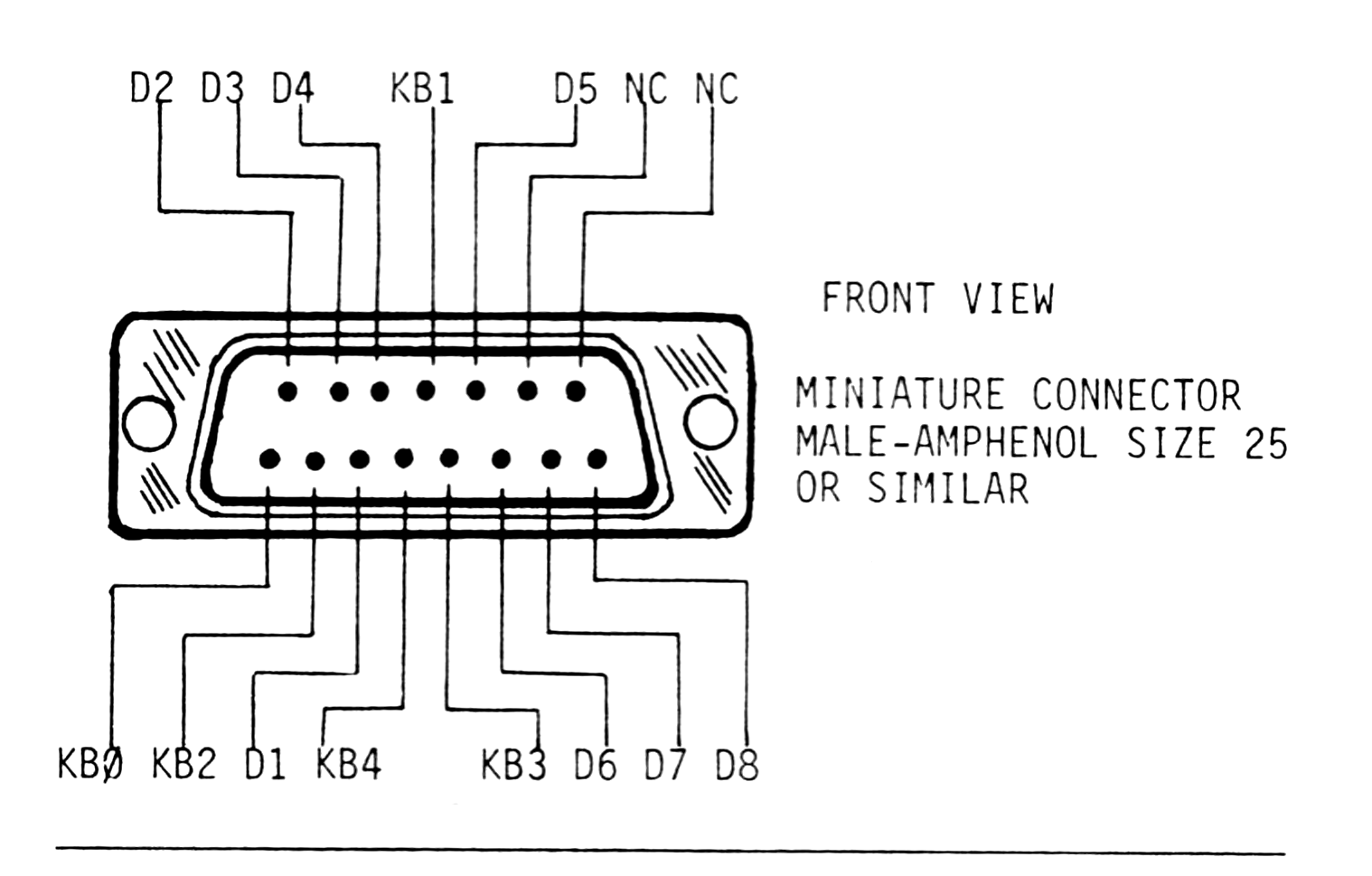
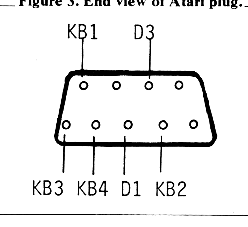
All that is required to convert the controller is to cut gently the copper foil on the circuit board as shown in Figure 1 and jumper this switch connection over to the edge marked KB4. However, the proper connections must be made at the 15-pin connector as shown in Figure 2. The connector is then hard-wired into the ZX81 printed circuit board as shown in Figure 4. The male connector is wired directly to the original keyboard socket connections by a short length of ribbon cable. This connector can be mounted into the top right-hand side of the case for good access.

Use great care when soldering to the socket pins since you will be very near small diodes which are sensitive to heat. Pre-tin your ribbon cable leads and solder bridges. Even though you do not need all the connections for the joystick, it is a good idea to wire all of the connections now since you may want to add a full-size keyboard later.
Guard against possible static discharge when handling the bare circuit board of your computer. Although it is rugged and can be reasonably handled, it is mainly made up of CMOS gates which can be permanently put out of action by a small static discharge. When working with CMOS circuits, I make it a policy never to wear sweaters or synthetic clothing or to work around plastic sheets, carpet, dogs, cats, or kids. Kids do not usually carry a lot of static charge, but they do have a tendency to drag all your parts into the floor when you are not looking. Try to discharge any static before touching the PC board. This can be done by touching a heavy metal object. Always use a high quality soldering pencil, preferably a grounded type, to insure against voltage transients from the iron.
Testing the Joystick
Plug the new controller into your connector and turn on the computer. A forward movement of the stick should produce a “7”and a backward direction will produce a “6.” Left and right should produce a “5” and “8” respectively. I wired the “fire” button to “9” because it was convenient, but you can wire it to the character you prefer.
If you only get a blink of the cursor and no character, either you have shorted one of the matrix lines to each other or one of the switches in the joystick is stuck closed. If you get a wrong character, you have misconnected one of the KB and D lines. Remove the controller from the connector; entry from the original keyboard should return to normal.
The only big disadvantage to this arrangement is that a diagonal direction cannot be achieved. I feel, however, that with the combined use of the fire button, this function could be easily programmed.
Rewriting Existing Programs for the New Joystick
The improved operation of the flight simulation program was so dramatic that I decided to rewrite all of my graphic programs to respond to the cursor keys.
My screen drawing program, “Sketch-pad,” is now a real joy to use. The three year-old from next door now loves “Sketch-pad,” but he would not even try it with the keyboard. The program is shown in Listing 1 for those of you who would like to try your artistic hand with the new joystick. The “fire” button is used to select between either erasing or drawing. Pushing the button causes the pixel to erase itself as it is moved. Then, by pushing the button again, drawing can be continued. This handy little feature allows you to erase any errors or move the pixel to another location to start another line.
Listing 1. Sketch-pad program.
  5 REM "SKETCH-PAD"
 10 CLS
 15 PRINT "DRAW"
 20 PRINT "Z=CLEAR"
 25 PRINT "USE FIRE BUTTON FOR ERASE"
 45 LET X=30
 50 LET Y=20
 55 IF INKEY$="9" THEN GOTO 135
 60 IF INKEY$="7" THEN LET Y=Y+1
 65 IF INKEY$="6" THEN LET Y=Y-1
 70 IF INKEY$="5" THEN LET X=X+1
 75 IF INKEY$="8" THEN LET X=X-1
 80 IF INKEY$="Z" THEN RUN
 85 PLOT X,Y
115 UNPLOT X,Y
120 PLOT X,Y
125 GOTO 55
130 IF INKEY$="9" THEN GOTO 60
135 IF INKEY$="7" THEN LET Y=Y+1
140 IF INKEY$="6" THEN LET Y=Y-1
145 IF INKEY$="5" THEN LET X=X+1
150 IF INKEY$="8" THEN LET X=X-1
155 UNPLOT X,Y
160 PLOT X,Y
165 UNPLOT X,Y
170 GOTO 130
Most Basic programs use one or two methods to control the movement of the PRINT or PLOT command. This is usually done using the INKEY$ function and usually lets some variable equal PEEK 16421. This location is the storage area of the value obtained from the keyboard scan done after each TV frame. However, the code that is stored in this location is only a value that lets the computer know which section of the keyboard is being pressed. That is, the character 5 would have its own value but the characters 6 through 9 would all have the same code since they are all located in the same keyboard section. This method is slightly faster, but will work with the cursor controls. The PEEK method will have to be replaced with the INKEY$ function as in Listing 2.
Listing 2. Rewriting the PEEK method.
100 LET X = PEEK 16421
130 IF X=(239) THEN LET Y=Y+1

Change To:

130 IF  INKEY$ = (your character) THEN
    LET Y=Y+1

Delete line 100
You will find that the trouble of removing the case back and the soldering of the connector will be well worth the effort when you see how easily the graphics now respond.
The $8.50 turned out to be a good investment.