
This column is devoted entirely to hardware repair and modifications to the Timex series of personal computers. In this feature I will show you on a monthly basis how to repair, modify, expand, and in general enjoy the hardware aspects of your personal Timex computer. In case you have any doubts as to whether I know what I’m talking about let me tell you a little about MY Timex…
I have a full 6.5 Megabytes of storage available to me on 3-8″ floppy disk drives, of which 2 are running DSDD (Double Sided-Double Density). The above is of my own design which will be available to the Timex user in December. The retail cost will be under $200 for Drive #1 and under $110 for Drives 2 & 3. My Timex has 7 controller boards for controlling lights, hardware, coffee pot, etc. I have 128KBytes of usable RAM, of which 64K can be used for program lines and the other 64K is used for variables etc. My little venture is worth about $5,400 at the present time. This is not to be considered “bragging”. I am just letting you know that much of what your friends say can’t be done with the “itty-bitty computer” I have already accomplished. Enough with what my computer can do. Let’s get on with making yours do more! This month’s project is really something special. Do you remember when your fellow computerist said that your computer was inferior compared to his? Maybe it is now, but it won’t be after a couple of issues of HORIZONS and a few hours per month reading my articles. I have designed a low-cost repeat key module that will work with either the Timex TS-1000 or the SINCLAIR ZX-81 (the same thing but with different packaging). 95% of all larger computers have repeating keys as standard equipment, but the Timex computer does not. So we will now proceed to upgrade our “little” computer…
NOTE!: T-S Horizons, Norris Radio & Electronics, T-Tech Industries LTD, their affiliates, or employees can assume no responsibility for damages arising out of the use/misuse of these articles. The reader must understand that any implementation of these projects is to be taken at the reader’s own risk.
Project: Repeat Key Module
Parts needed: 10 K Miniature potentiometer(1)
              SPSD Miniature toggle switch(1)
              ½ Watt 1K resistor (1)
              100 Microfarad electrolytic
               capacitor (1)
              74LS244 Non-inverting,
               tri-state octal bus driver(1)

Tools needed: 25-30 Watt grounded soldering
               iron
              40/60 Rosin core, fine guage
               solder
              Desoldering tool (about $7.00
               at Radio Shack)
Let’s get started! Connect the circuit as shown in Diagram A-1 being sure to make good clean solder joints. Remove the bottom of the computer by removing the screws and rubber feet as shown in Diagram A-2. Set the screws and the rubber feet aside; you will need them later. Remove the 2 silver-colored screws from the P.C. board and lift the board up and out about ½ inch. Disconnect the keyboard ribbon by gently pulling the keyboard ribbon connector out of its socket. Place the top and bottom case halves where they will not be disturbed.
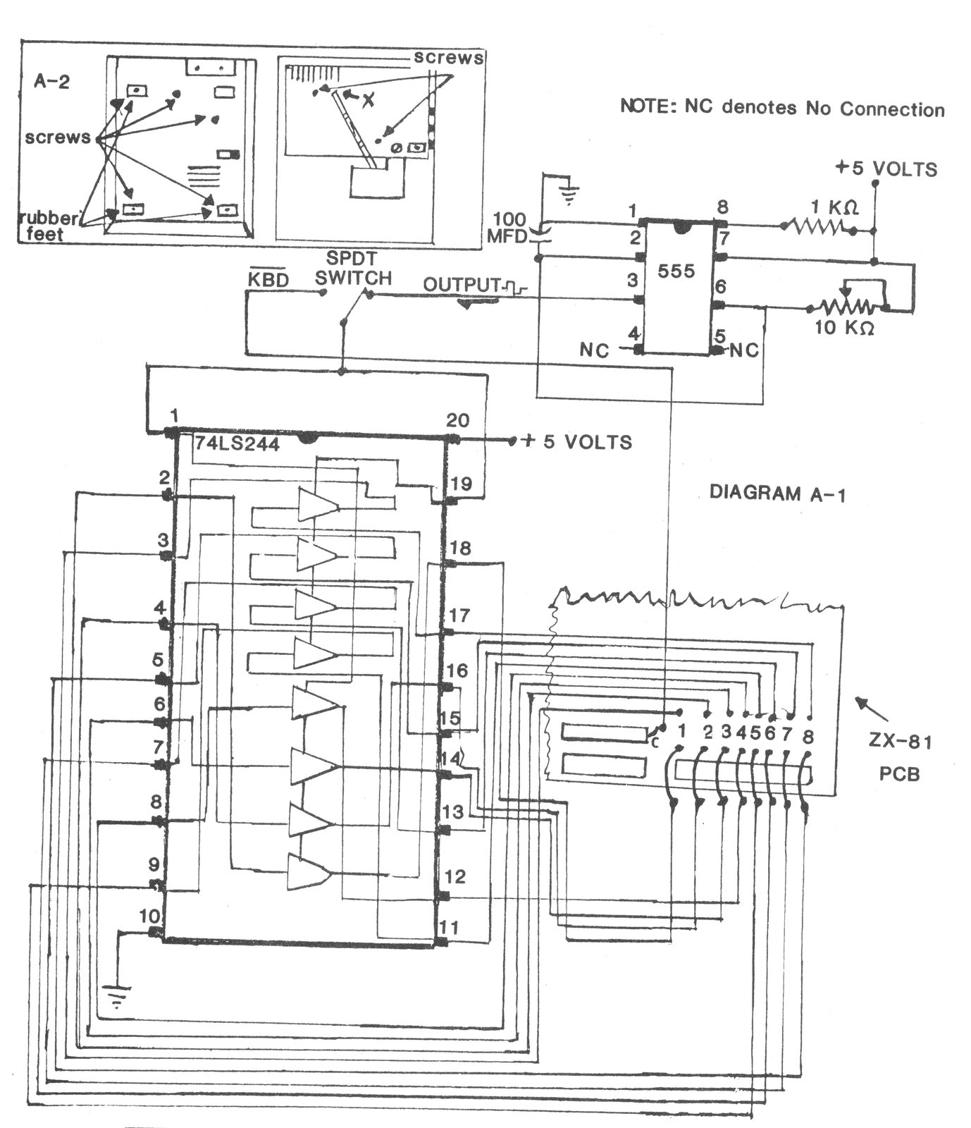
Using a small screwdriver, slowly desolder and pry out the eight 1N418 diodes from the PCB and lay them aside. Using the diagram for a guide, connect the wires from the 74LS244 bus driver to the holes shown in the diagram that were formerly occupied by the diodes. Using a volt-ohmmeter, find a +5 volt source on the ZX-81 or TS-1000 PCB. Having located it connect all +5V wires from the repeat module to that source. (Note: Avoid the +5V trace to the modulator or severe TV interference will result). Refer to Diagram A-2 and find the “X” that is in the picture. It has an arrow pointing to the solder pad at the end of the little metal strip. Connect the 2 grounded pins to this point.
Now for the test…plug in the computer and place a wire jumper between a metal contact on the small female keyboard connector (any one will do) and a metal contact on the large female connector. A character should appear and begin to repeat itself. If it doesn’t, turn the 10KΩ potentiometer to different settings. If it still doesn’t, check all connections and check all solder joints. (Note: Make sure the switch is in the “REPEAT” mode.)
Locate an area on the uppercase half and mount the select switch. (Note: Make doubly sure that there is nothing behind the switch on the PCB that will interfere with the switch casing.) See the potentiometer at the repeat rate that suits you best. Disconnect the wire jumper. Using the 2 silver-colored screws, mount the PCB back in the uppercase half. (Did you remember to reconnect the keyboard?) Replace the bottom case half and reinstall the 5V screws and 3 rubberfeet. I hope that you enjoy the use of the repeat key. (Suggestion: If you need to type in a long REM statement, place a book on the space key and the rest is automatic.)
For those of you who are scared by the looks of a soldering iron, I will build and install the repeat module for $30.00. Also, for those of you users who have the above phobia and a subscription to TS-HORIZONS knock $5.00 off the above price, ($25.00!). If you just want the module and feel adventurous enough to install it yourself send $19.00. Well, until we solder again next month…
HAPPY COMPUTING!
T. Norris
144 Terry Drive
Slidell, LA 71458