
Rick has allowed me to submit article material for this extremely useful publication, and probably the best ‘first’ item to share with you is a simple loading aid that has become a fixed add on in my own system. If you build and use it yourself for a while, you will find that trying to get along without it will be difficult. It first of all incorporates a simple on/off switch to eliminate the plug-in connector. Frequent plugging in and unplugging eventually wears out the plug receptor jack.
Loading difficulties arise from a number of reasons and the most predominate is that from heating. One of the 40 pin chips inside the TS1000 takes the place of a dozen or so smaller ones and although it allows the physical size to be much smaller, the heat is too much for it alone to dissipate. All new production units are equipped with a small heat radiator that is permanently affixed to the chip and has, as far as I have seen, done away with the majority of loading problems or more specifically, crashes.
Another problem is with the tape player you use. Most that I have seen (in our local user group), are cheap and inadequate recorders that are a bit poor in rendering not only a good output signal, but even other unseen electrical problems such as ground loops! This problem was noticed when the player was left running with no cassette inside. After touching the EAR plug to the EAR jack on the tape player, a very high pitched sound was noticed. Almost inaudible, you may or may not even hear it or see it on the screen. More often than not, the computer will not be affected by it but depending on the number of devices (MONITOR, PRINTER, COMPUTER, TAPE PLAYER, ETC.) you have running, it may become a real annoyance. This loading aid will serve to eliminate these and other inconveniences you might experience.
All parts needed for this project may be obtained from Radio Shack and very little needs to be said about its construction. The only interesting component is the Light Emitting Diodes. These are connected back to back such that if any clipping occurs, it occurs equally among the signals on line. They do not begin to conduct until the signal reaches about 1.2 volts. When conduction occurs, they begin to glow. They can glow brilliantly if enough signal is pumped down the patch cord by turning the tape player volume up very high.
Take the plastic enclosure and drill holes to receive th 1/8th inch female phono jacks. Drill 3 on one side, 2 in the rear and one on the left. The lid of the enclosure should be drilled to hold the 2 switches, and LEDs . Wire and solder as shown.
Check your wiring and plug it in to the system. Load a program and monitor the brightness level of the LED. I have perfect results when it is set such that it just begins to glow. Yours may differ, but even with poorly recorded tapes you should be able to adjust the tape player volume to cause the indicator to turn on. Now, use it for a month and remove the loading aid. See if you can conveniently adjust your recorders level without it!
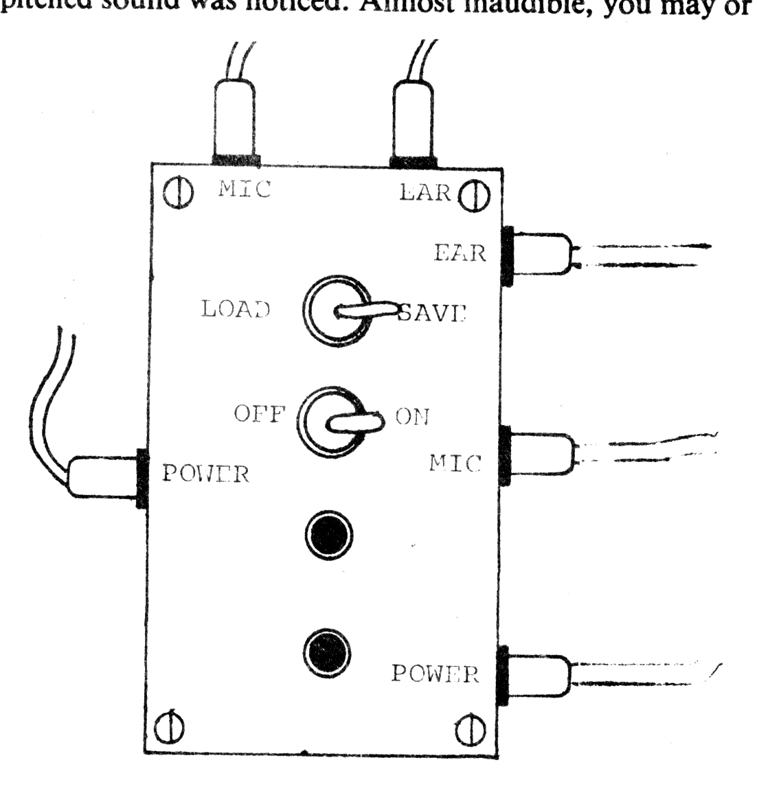
NOTE: The SAVEing LED can be mounted inside the case.
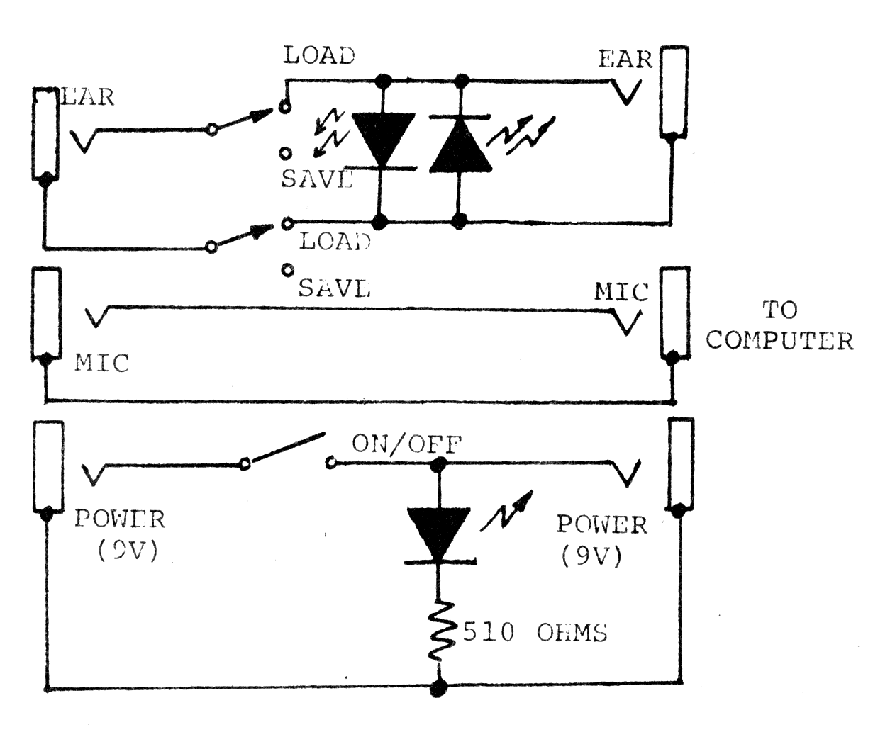
LIST OF MATERIALS
- 1 – DPDT Mini Switch
- 1 – SPST Mini Switch
- 3 – Light Emitting Diodes
- 6 – 1/8th inch mini jacks
- 1 – 510 OHM resistor 1/4W
- 1 – Small Project box