
To start this month’s instalment, we will clear up the increased RF interference on the display and discuss alternative power supplies.
DIRECT VIDEO
There have been several articles describing how to interface a ZX81/TS1000 to a monitor instead of a TV. The advantage, of course, is the elimination of RF interference and a much sharper and steadier picture. The most useful articles have been:
Ciarcia    BYTE 8 (6) June 1983 p.462
Nachbaur   SYNCWARE NEWS 1 (5) June 1984 p.14
Pence      COMP. & ELECTR. 21 (5) 1983 p.82
Lewart     SYNC 3 (4) 1983 p.50 & (5) p.42
There have been several others but in general not so useful as the four listed above. The procedure is nearly always the same. The composite video signal from pin 16 of the ULA is buffered by an NPN transistor in an emitter-follower configuration. The output is fed to the 75ohm input of the monitor (Figure 1). Ciarcia’s article illustrates the use of the lower power 2N3904 transistor. Some articles discuss circuitry for the generation of inverse video.
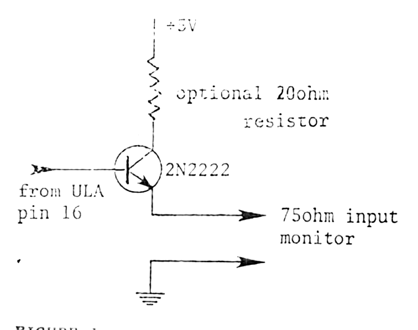
This circuit is the same as the one in Fred Nachbaur‘s article — you might wish to add his simple video cleanup/reverse circuit as well.
If you look inside your ZX81/TS1000 you will see next to the ASTEC RF modulator (which you can remove if you wish), a row of six holes (Figure 2).
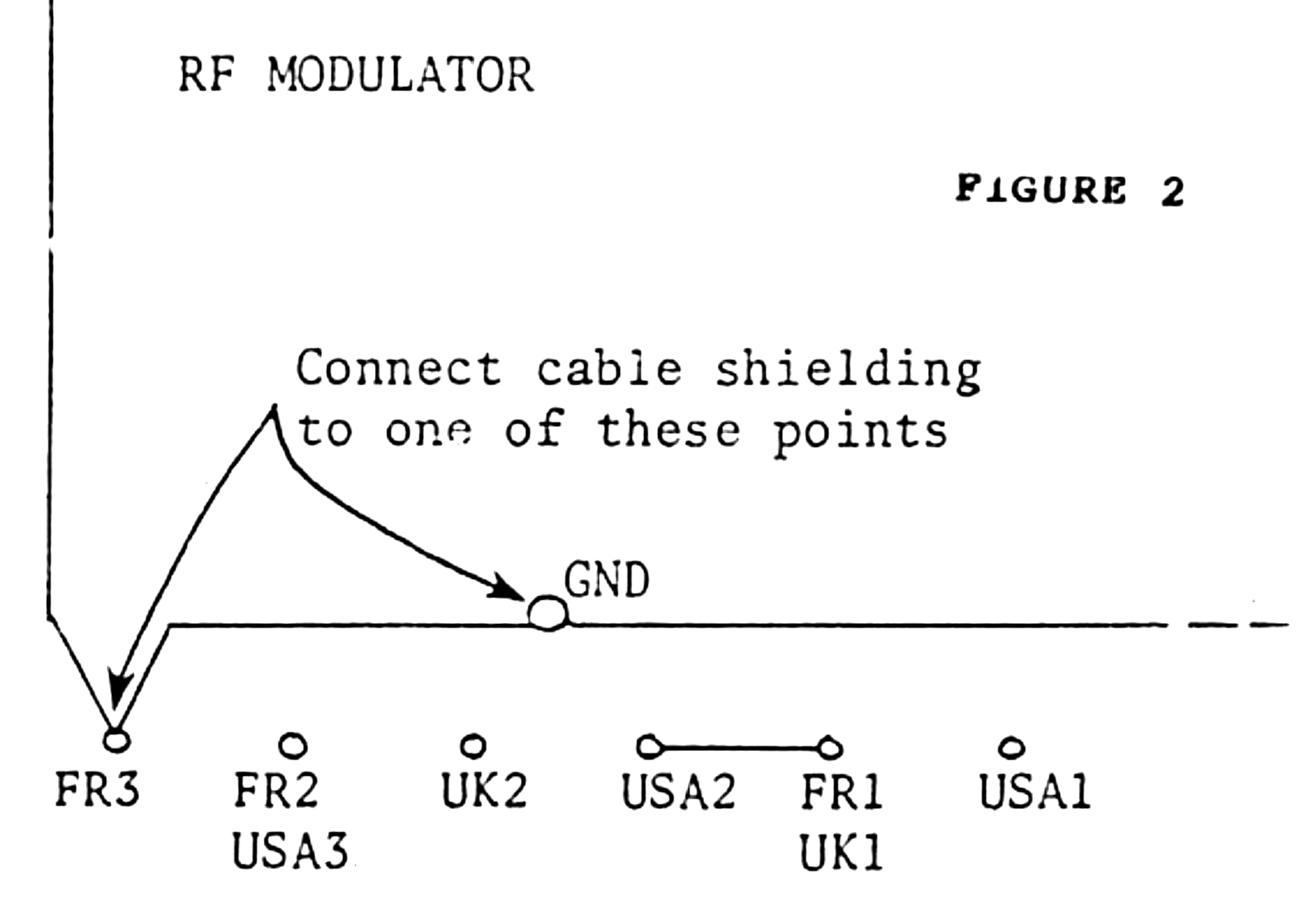
The connection between the cable-shielding (ground) and the ZX81 board can be made as shown in Figure 2. The base lead of the NPN transistor is mounted in the UK2 hole, the emitter lead is soldered directly to the monitor cable, and the collector is connected via a 20ohm resistor to the USA2 or FR1/UK1 hole. The cable may be obtained from Radio-Shack (#42-2367 $1.89). The difference in the display is remarkable. Green or amber 12″ monitors can be obtained for less than $100. (For example, K-Mart recently had the BMC monitor on sale for $84.)
POWER SUPPLY
By the time you connect four RAM packs, an NVM board, and a Centronics I/F, etc. to the expansion board the original power supply runs very hot, even after removing the regulator from the case and adding more effective heat sinking. So a new supply was required.
A useful approach is to build a more powerful 9-10V supply and then place separate 5V regulators on individual boards as needed. As it turned out, however, I used the original 9.75V supply for the RAM packs and built a separate well-regulated 5V 5A supply. The approach worked well enough. The 5V supply was later replaced by a surplus switching power supply from Jameco because I needed +12V and -12V as well. Jameco and many other companies often have surplus power supplies on offer at very reasonable prices. For example, B.G.Micro (P.O.Box 280298, Dallas, TX75228) have a multivoltage switching power supply for $37:50. Many others are advertised periodically in the popular magazines. Finally, an article by Steve Ciarcia in BYTE December 1983 p.36 described the use of MOV’s to protect your system from transient high voltages. Considering how cheap these MOV’s are, it’s worth doing.
SOME POINTS ARISING
The COMPUTER CONTINUUM board is no longer supplied by Eric Reiter but it is available from Budget Robotics & Computing, P.O.Box 18616, Tucson, AR 85731, for $40 post paid. The price includes the ZX81 connector.
Other buffer boards are available. An example is Kit #K2615 from Velleman UK, P.O.Box 30, St.Leonards on Sea, East Sussex TN37 7NL, UK. Alternatively, Board #84054 from Elektor, Elektor House, 10 Longport, Canterbury CT1 2BR, UK. (This is a simple board with socketing for three 74LS244, one 74LS245, one 74LS138, and one 74LS00. Connection to various peripherals is left up to you.)
If you need any extra ZX81/TS1000 CPU boards to incorporate in a banked memory system or whatever, BNF Enterprises (P.O.Box 3357, Peabody, MA 01961-3357) currently have them on sale at $18:88.
The foil diagrams shown last month were not actual size as stated, but were reduced in reproduction.
If more banks — beyond the four catered for by the ‘LS74 and ‘LS139 — are required, then a quad ‘LS175 with up to two ‘LS138’s will provide up to 16 banks of 16K each. The problem with this is, of course, that sometime or other it all has to be loaded and it is vunerable to a system power failure. The better approach is to limit the number of banks and provide additional nonvolatile mass storage. The banked RAM can then be used to support the mass storage by providing fast access cache memory.
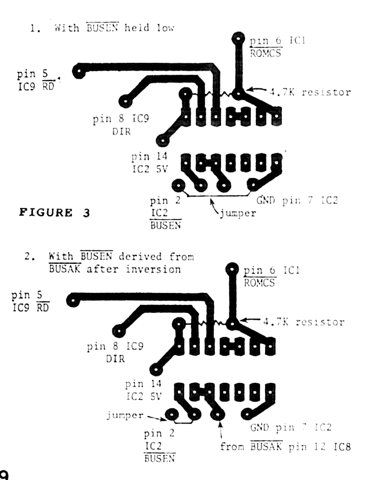
In Part 2, Figure 2 section 5, the BUSEN signal is input at pin 2 of the IC2 socket not the IC9 socket as stated. Normally this can be held at ground by jumpering as shown below (Figure 3). The board has been changed slightly to facilitate this. If you plan to use two processors, or require DMA, then the BUSEN signal should be derived from the BUSAK signal from the ZX81/TS1000 board by inversion.
STORING NUMBERS
In thinking about an operating system for this banked memory system, I found that at some point it was necessary to convert a decimal character string into a two-byte integer. Fortunately there are routines in the Sinclair operating system for the conversion between the different formats in which numbers are stored. See in particular the Complete ROM Disassembly by Logan and O’Hara.
Possible formats for numbers are:
INTEGER:         byte 0-255 decimal
                 word 0-65535 decimal

FLOATING-POINT:  any number between 10⁺³⁸ and
                 4 x 10⁻³⁹. Only 9-10 digits
                 stored and only 8 displayed
                 Each number occupies five
                 bytes

STRING:          a string of character
                 codes representing decimal
                 digits 0 through 9
Figure 4 illustrates how to convert between the different formats using system ROM calls.
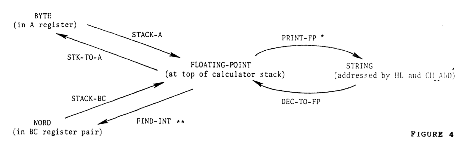
* Actually prints the string at the current position on the screen — which can be changed using the routine at 08F5hex with the line in register B and the column in register C.
** Note that since the result is in the register pair BC, the result can be displayed by using the command PRINT USR …
ADDRESSES
Routine      hex      decimal
                     MSB  LSB
STACK-A      151D     21   29   5405
STACK-BC     1520     21   32   5408
STK-TO-A     0C02     12    2   3074
FIND-INT     0EA7     14  167   3751
PRINT-FP     15DB     21  219   5595
DEC-TO-FP    14D9     20  217   5337
Try the following two examples to illustrate the use of these routines:
EXAMPLE 1
In this example a two-byte word will be moved to the calculator stack and then printed. The two bytes 35 (MSB) and 40 (LSB) represent the number 9000 (i.e. 35 x 256 + 40 = 9000).
Store the two bytes in a REM statement at 16514 and 16515. First enter a REM statement at line 10 with any two characters following the REM. Then:
POKE 16514, 40
POKE 16515, 35
Enter the following machine code at a convenient location (for example, above RAMTOP or in the 8-16K block as below):
8192   237   75  130   64  LD BC (16514)
8196   201                 RETURN
Now enter PRINT USR 8192 and return. The result shows that BC register pair contains the decimal integer 9000. Now add the additional instructions:
8196   205   32   21       CALL STACK-BC
8199   205  219   21       CALL PRINT-FP
8202   201                 RETURN
Enter RAND USR 8192 and the same result (9000) is printed — the two-byte integer is converted to floating point, placed on the stack and then printed.
EXAMPLE 2
In this example a string of decimal characters will be converted into a floating-point number and then printed.
Enter a REM statement with any number less than 65535 followed by an asterisk. For example:
10 REM 9000*The machine code is:
8192    33  130   64       LD HL 16514
8195    34   22   64       LD (CH_ADD) HL
8198   126                 LD A (HL)
8199   205  217   20       CALL DEC-TO-FP
8202   205  167   14       CALL FIND-INT
8205   201                 RETURN
Enter PRINT USR 8192 and the number in the REM statement will be printed. Instead of calling FIND-INT, call PRINT-FP and use RAND USR 8192. The result will be the same. Use of the single byte routines limits the size of the integer to 255 — larger numbers will result in the error report B. Just for interest, using PRINT-FP, try a string such as 1E2 or even 1.2E-2 in the REM statement.
Next month we will construct a directory.
Note: Type-in program listings on this website use ZMAKEBAS notation for graphics characters.